We found the problem on the calibration of our Maslow CNC when running some test cuts. While cutting horizontal lines, it curves down about 1-2 cm in the center, even when we set the correct measured distances for the CNC in the “groundcontrol.ini”file.
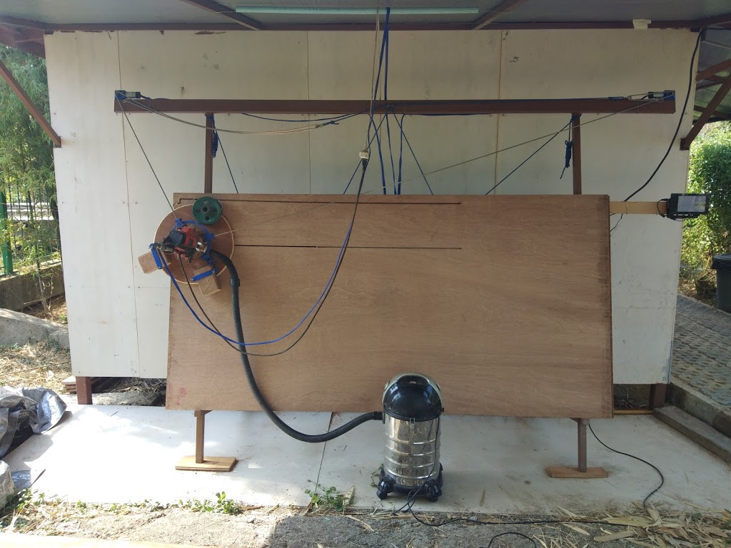 |
| Horizontal straight line curved down. |
This really isn’t a surprise. We’ve done a lot of work in the past in colorspace calibration of optical devices, and as a general rule, when you are calibrating, you need to run tests, measure the results, and adjust the input parameters to achieve the desired output results. The Maslow CNC calibration seems to be oriented only towards measuring the input parameters carefully and hoping that the output is what you want. The “closed loop calibration” approach of feeding errors in the output back into adjust input parameters has always worked well for us in other fields, so we decided to implement it here ourselves.
So we created a “refine_calibration_parameters.py” script to adjust the input parameters based on measured output results. To be specific, the script works as follows:
- First we calibrate as well as possible by measuring everything carefully in order to get the machine within a centimeter or two of calibrated over the entire area.
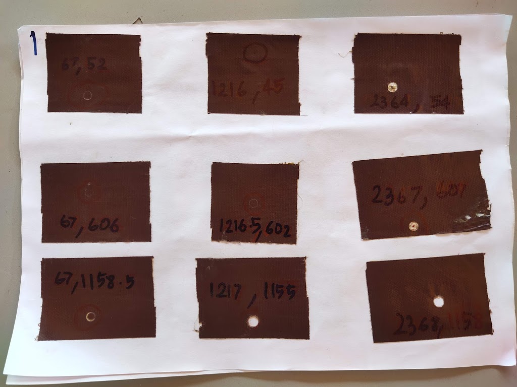
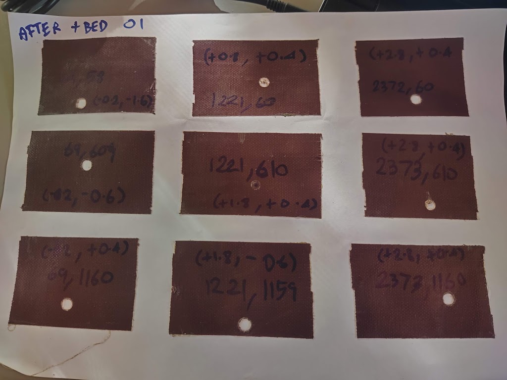
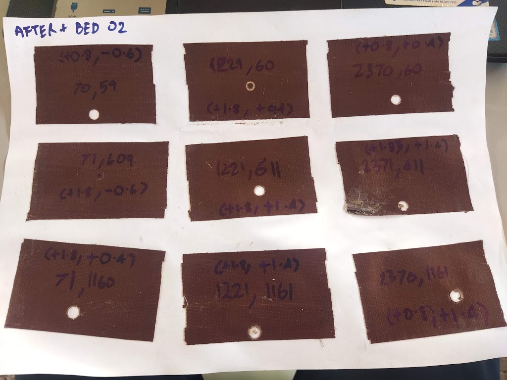
- We created a simple GCode file that tells the CNC to go to a number of known points and make a mark on the surface. Any set of scattered points would do, so we did a 3×3 grid of left,middle,right columns and upper,middle,lower rows as follows:|
0 1 2
3 4 5
6 7 8
To avoid wasting wood, we simply put tape on the surface of the wood close to where the expected marks are and told the CNC to just touch the surface. The marks were easily visible in the tape with no noticeable marks on the wood.
We put the tape on 9 expected positions on wood. - After running the GCode file, we measured the distance from left and top of the edge of the plywood to each of the 9 marks that the CNC made. This gives us a pairing between where the CNC thought it was going to make the mark and where it actually made it. This information (where the GCode told it to go vs where it actually went for each of the 9 marks) was put into a file called “Calibration Measurements.ini” for our calibration script.
- The script we wrote then reads the “groundcontrol.ini” CNC configuration file used to cut the GCode file as well as the information on target vs actual from “Calibration Measurements.ini”.
- An interesting little twist is that it made less sense to tweak the actuals to be closer to the target (because this would require running a new cut to check). Rather we compute the chain lengths that the CNC would have used given the “groundcontrol.ini” file configuration at the time of cut to achieve the given targets, and then say “how should we tweak the configuration so that those cable lengths would have corresponded to the actually measured values?” In other words, we tweaked the targets to the actuals given the chain lengths that were actually used for the calibration marks. This can be done thousands of times per second without running any additional cuts on the machine.
- This is done using a standard multi-variable optimization approach. We create a cost function (sum square Euclidean distance between target points and actual points) and then use Gauss-Newton to adjust the configuration parameters to minimize the cost function (i.e. make the target and actual points line up). The main parameters that we optimized are:
MotorSpacingX = The horizontal distance between the center of the motor shafts in mm
MotorOffsetY = The vertical distance between the motor mounts and the zero position on the cutting bed
RotationDiskRadius = The distance between where the chains attach to the sled and the center of the router bit in mm
ChainSagCorrection = A single parameter to model the amount of chain sag that occurs when the chain is mostly horizontal. One would expect this to be affected by the sled weight and chain weight. - We added a few additional calibration parameters like the horizontal offset of the motors relative to the cutting bed, as well as an angular offset between the line connecting the 2 motors and the cutting bed. Personally, I would have included these as calibration parameters in the MaslowCNC firmware, but they didn’t. These values are very small by design of the machine, but still adding them to the mathematical model allowed the optimizer to more accurately compute the above calibration parameters.
- Finally, after minimizing for a few seconds, the script produces a new “groundcontrol.ini” file that replaces the optimized parameters in order to better achieve the lineup of actual and target positions.
You can replace the input “groundcontrol.ini” with the output and run the calibration again to see how much it improved.
Here is before calibrating:
 |
| Before calibration result, middle column shifted down about 1 cm. |
And here is after the first 2 iterations:
 |
| First iteration. |
 |
| Second iteration. |
Updated :
“RefineCalibrationParameters” script were merged to Master in GroundControl on the MaslowCNC github repo.
The “Calibration Measurements.ini” file example was pasted down here. feel free to copy and change the actual position referenced from top-left in mm unit.
[global]

numpositions = 9

[actual_positions]

x0 = 67
y0 = 52

x1 = 1216
y1 = 45

x2 = 2364
y2 = 54

###

x3 = 67
y3 = 606

x4 = 1216
y4 = 602

x5 = 2367
y5 = 607

###

x6 = 67
y6 = 1158.5

x7 = 1217
y7 = 1155

x8 = 2368
y8 = 1158

[target_positions]

tx0 = 69.2
ty0 = 59.6

tx1 = 1219.2
ty1 = 59.6

tx2 = 2369.2
ty2 = 59.6

###

tx3 = 69.2
ty3 = 609.6

tx4 = 1219.2
ty4 = 609.6

tx5 = 2369.2
ty5 = 609.6

###

tx6 = 69.2
ty6 = 1159.6

tx7 = 1219.2
ty7 = 1159.6

tx8 = 2369.2
ty8 = 1159.6
Is there any chance of sharing the python script you created? I am not the best at computers and cannot afford a traditional CNC machine but I would like to be able to use the maslow for tasks more precise than I am able to now. Thank you in advance!
Nice approach
The scripts can be found in the master branch of GrounControl on github, but in what format do i make the {put into a file called "Calibration Measurements.ini"}?
In what order are the scripts run?
Thanks for taking a look at our blog. As mentioned by the commenter below, we have submitted our calibration script to the MaslowCNC github repo. I'll try to update the post above with a link to it in the next few days.
Thanks for your interest in our blog. As you mentioned, the script can be found in GroundControl on the MaslowCNC github repo.
There is only a single script that needs to be run. It is called "refine_calibration_parameters.py". The other files are just code files that get imported by this script.
The "Calibration Measurements.ini" file contains a bunch of target locations that your sample gcode tried to mark, and the actually measured mark locations (measured from the upper left of your work space).
For some reason, the sample file didn't make it into the github repo. Thanks for pointing this out. We'll try to get them to add it soon. In the meantime, I'll ask my collaborator to post an example here.
Thank you for your kind reply. You blog is amazing and will give me days/weeks to read, as we have allot of interests in common.
I added example of "Calibration Measurement.ini" in the post. You can copy and change the actual position which were referenced from top-left in mm unit.
I really appreciate you sharing this information for a better calibration for Ground Control. I have a Windows 7 machine as my CNC computer and Web Control will not work with Windows 7.
I could not find a way to download the files from GitHub so I copied them and saved with the appropriate name. I took your sample data posted in this blog and saved it as "measurement.ini". I created a blank file named "groundcontrol-mod.ini" and assume this is built after the script has finished. I then installed Python and it works when I call it generically.
I then put all the necessary files in the same directory as Python and ran this script:
python3 refine_calibration_parameters.py groundcontrol.ini measurement.ini groundcontrol-mod.ini
The script was suggested by Bar and I have very little experience with Python. Running the above script returns an error:
File "", line 1
SyntaxError: invalid syntax
Does this mean there is something wrong with the code for refine_calibration_parameters.py?
Thanks for your help.
Got it to compile. Thanks!