And now we get to start assembling the fuselage…
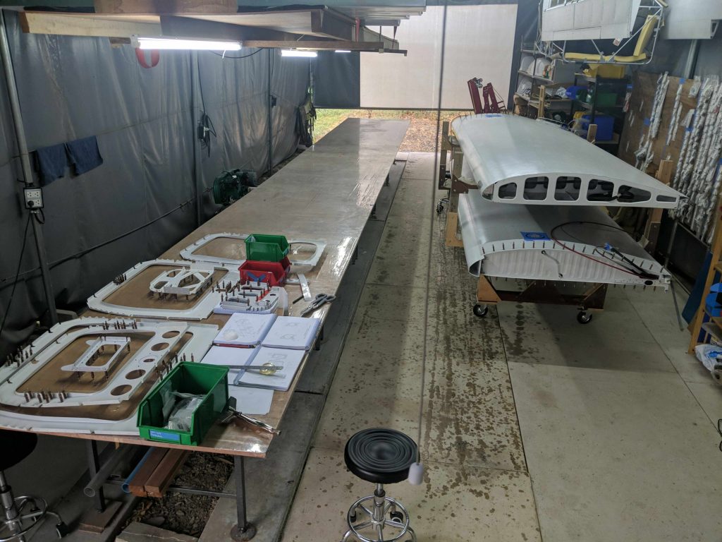
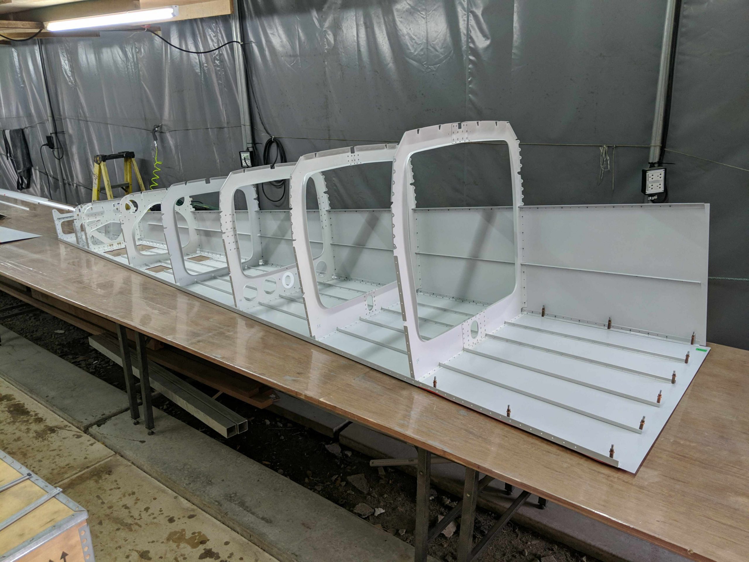
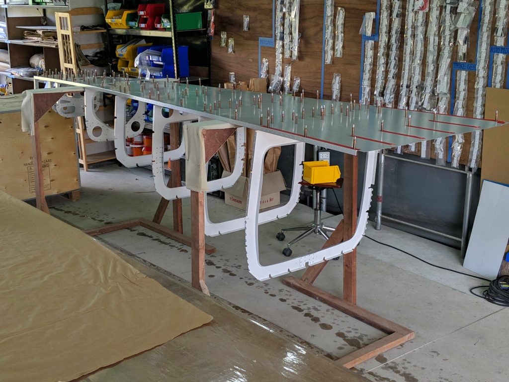
We clear the wings off the long work table to make space for the fuselage build.
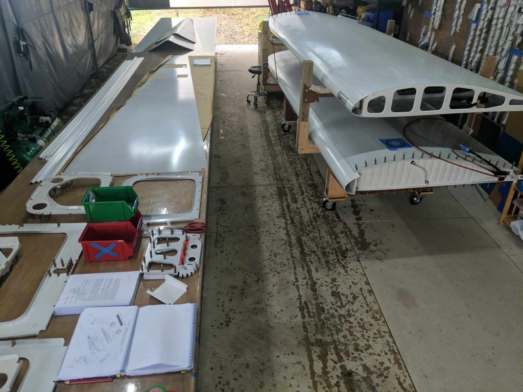
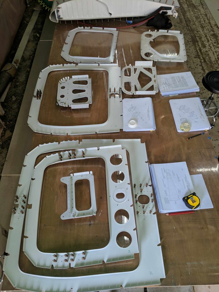
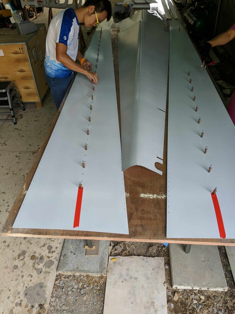
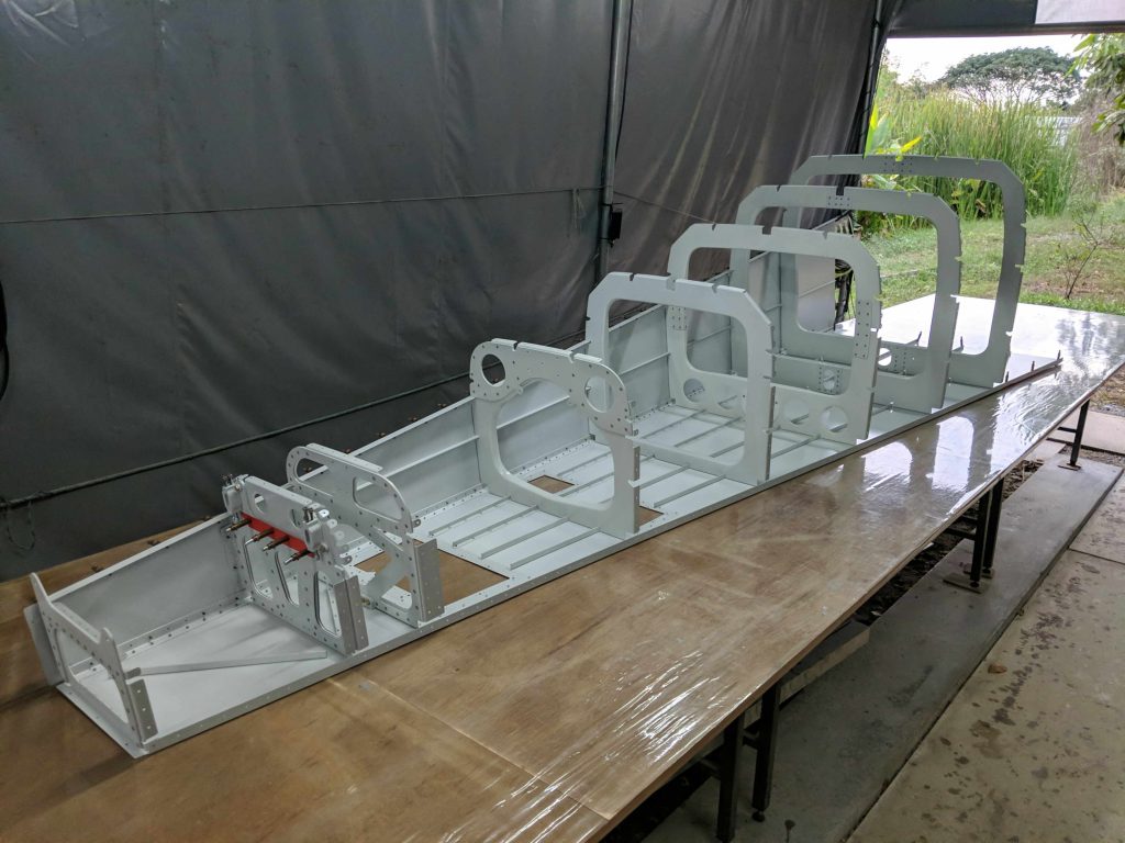
Then we layout the fuselage tailcone skins
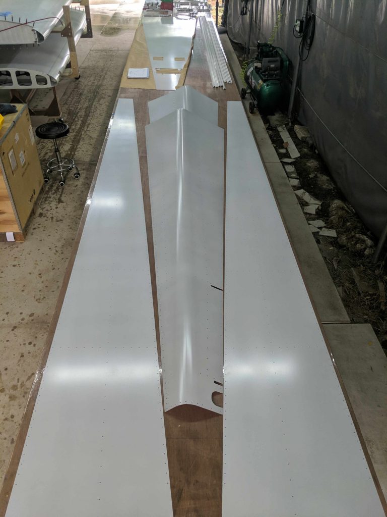
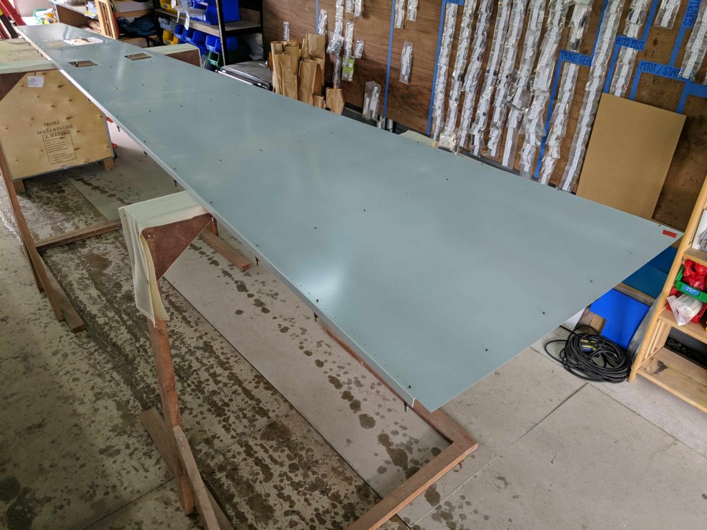
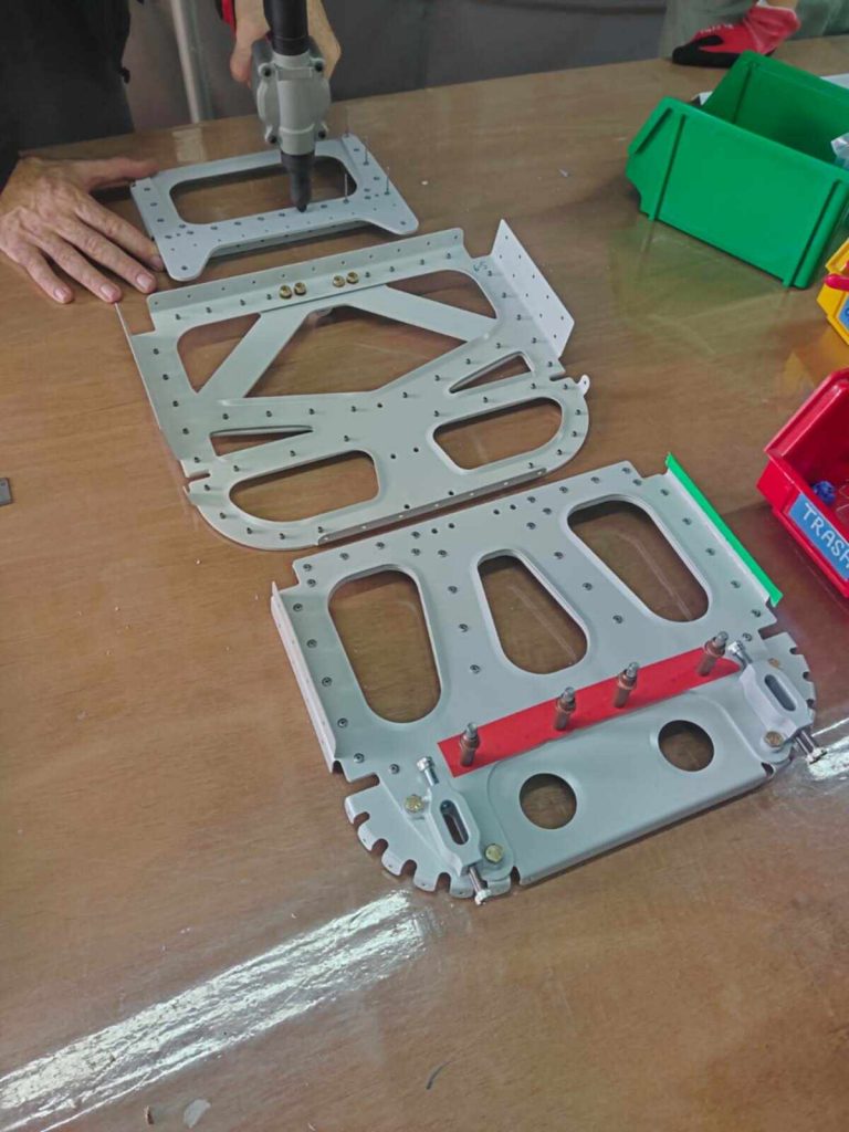
We start assembling the tailcone by attaching the fuselage bulkheads to the bottom skin while the bottom skin is resting upside-down on sawhorses
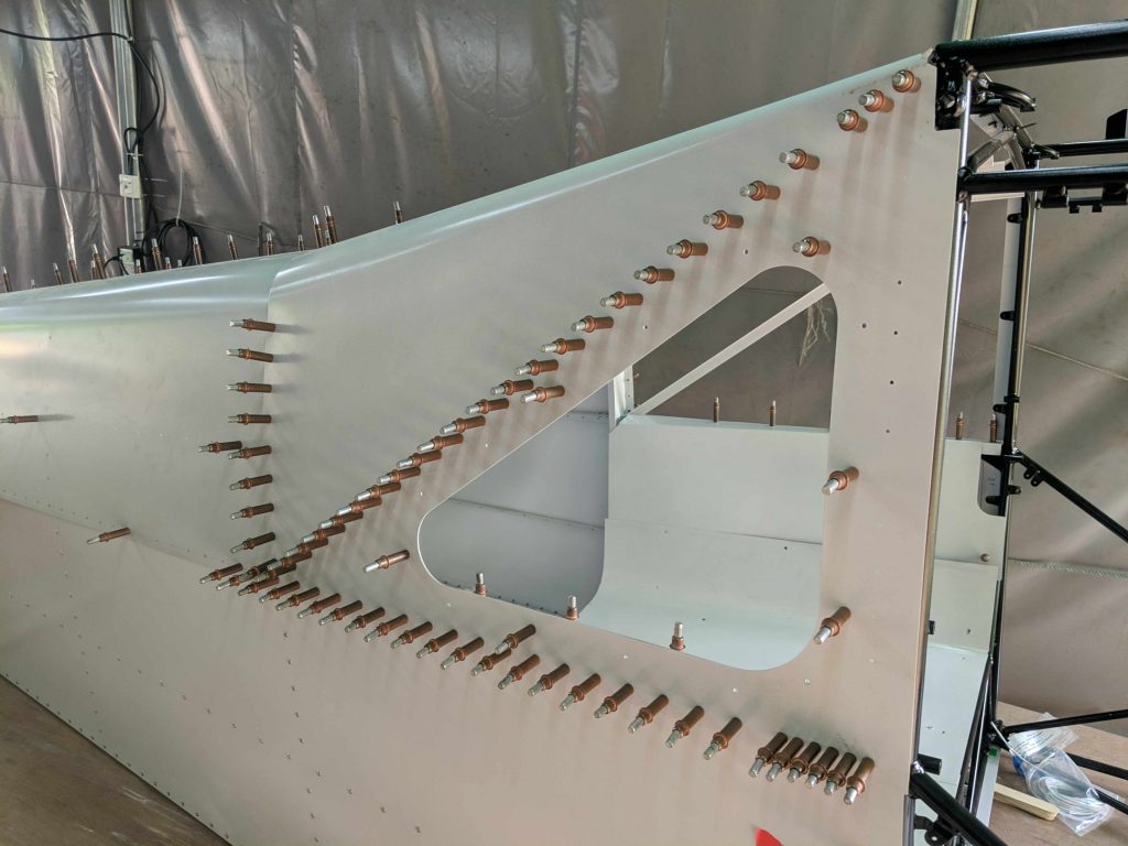
Then we Cleco and rivet the stringers onto the side skins
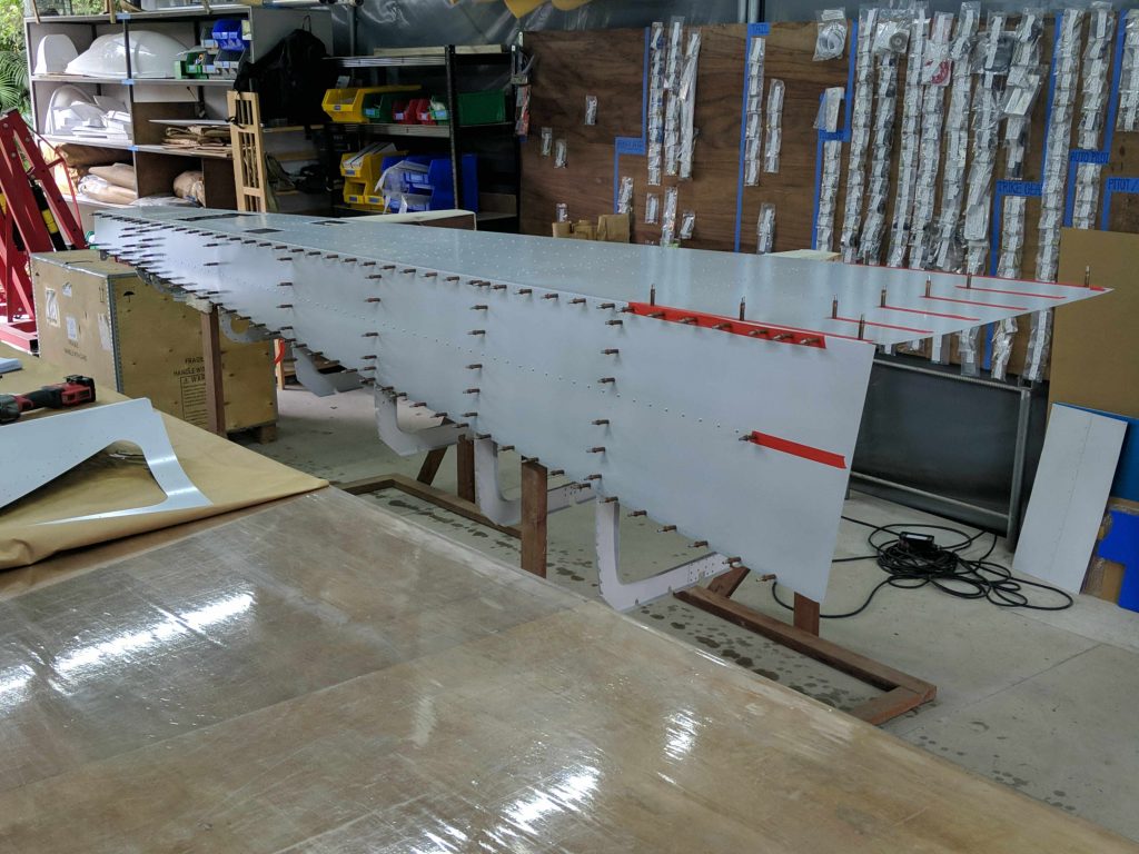
And Cleco one side skin onto the tailcone assembly
Then it moves onto the table
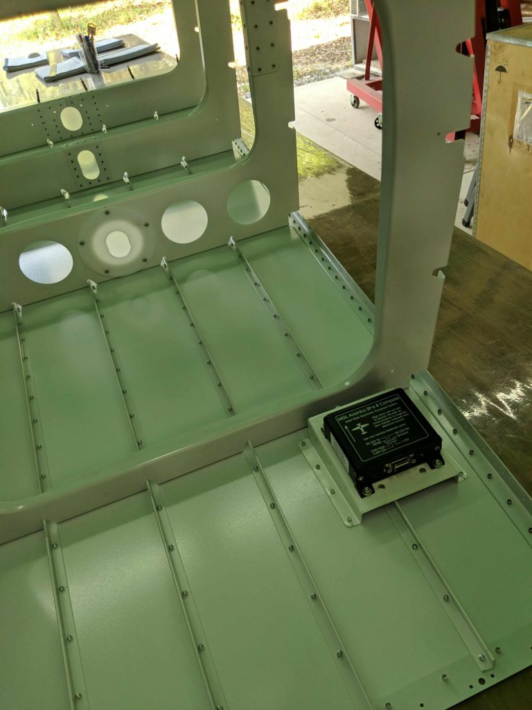
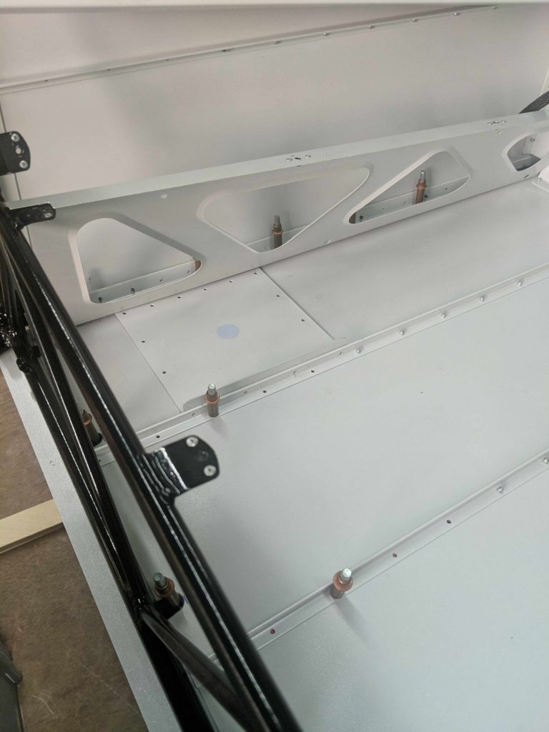
This seems like a good time to mount the avionics magnetometer. It needs to be kept away from any ferrous metals (like steel) and since the cockpit cage and landing gear and engine mounts all have a lot of steel in them, it is recommended to mount it back in the tailcone. We mounted ours where the Rans documentation recommends mounting the Garmin one, and we built our own aluminum mounting bracket with nylon strips underneath which we drilled and tapped to turn into a sort of nut plate:
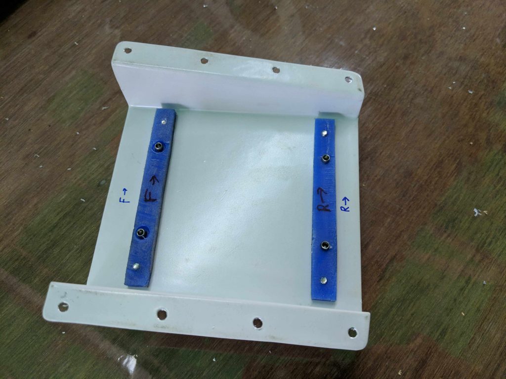
The nylon nut plate strips are mounted with aluminum rivets making the whole thing non-ferrous. We ordered aluminum screws and nylon washers to mount the actual magnetometer, and then ran the power and CANbus wires along the side to the front.
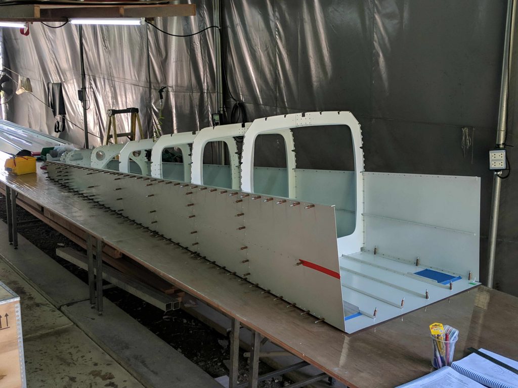
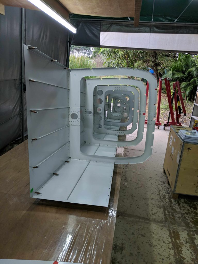
From there, it is time to put on the other side skin
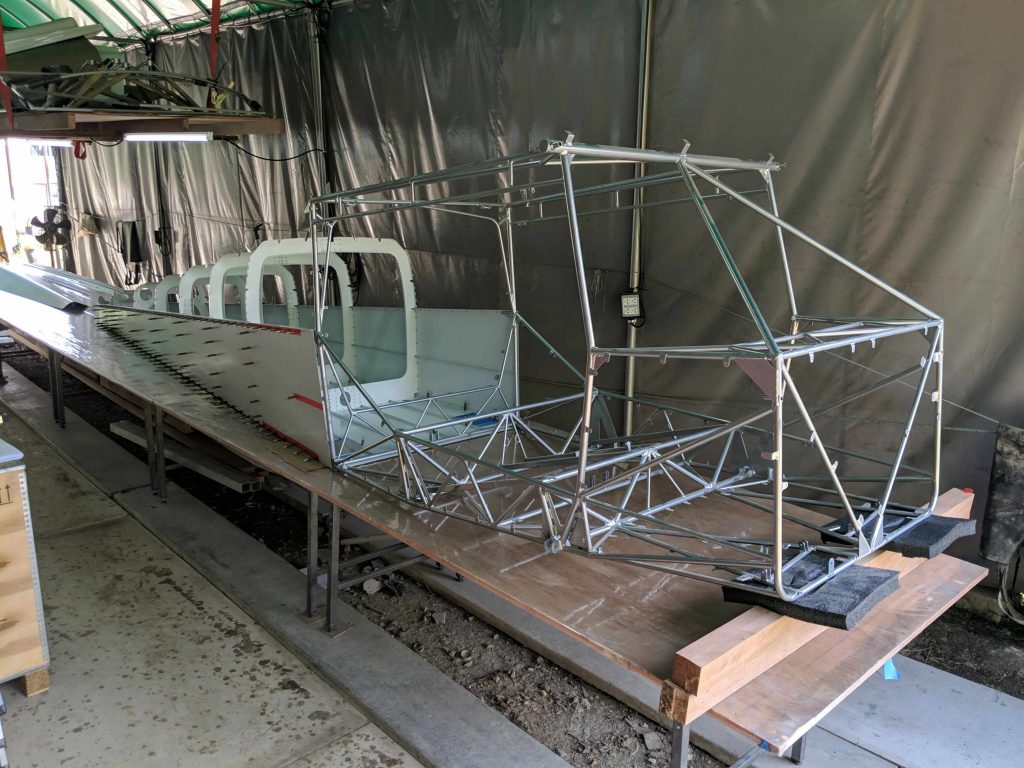
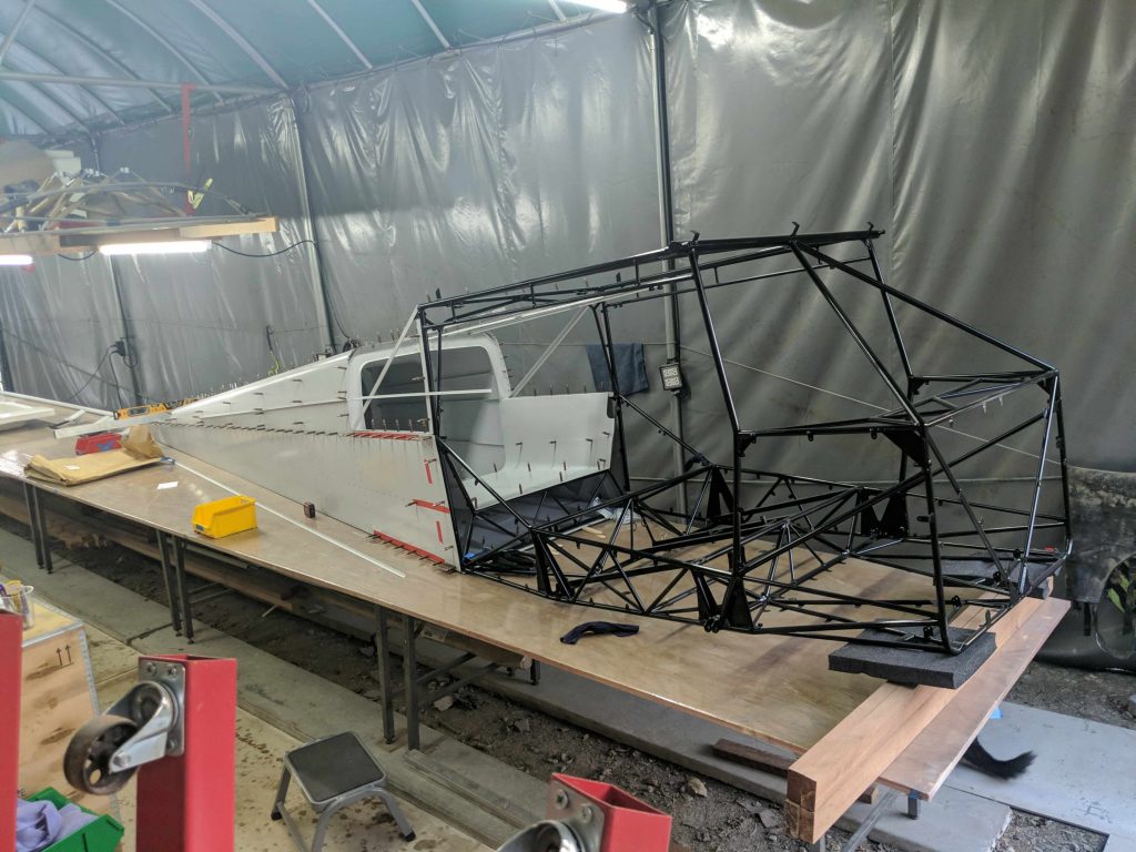
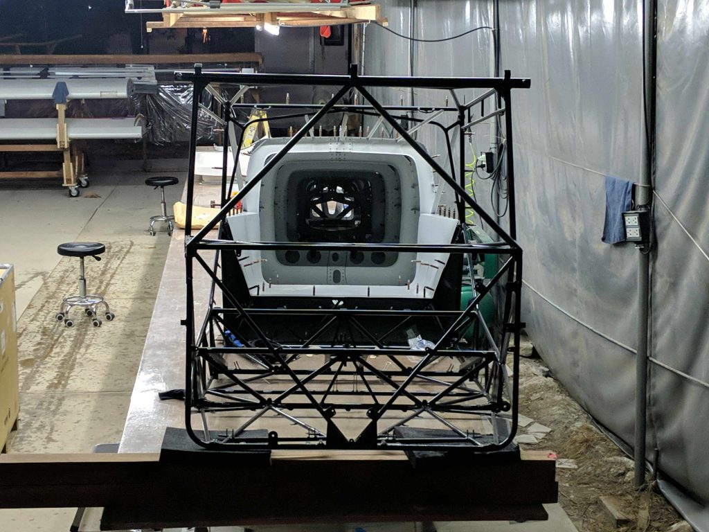
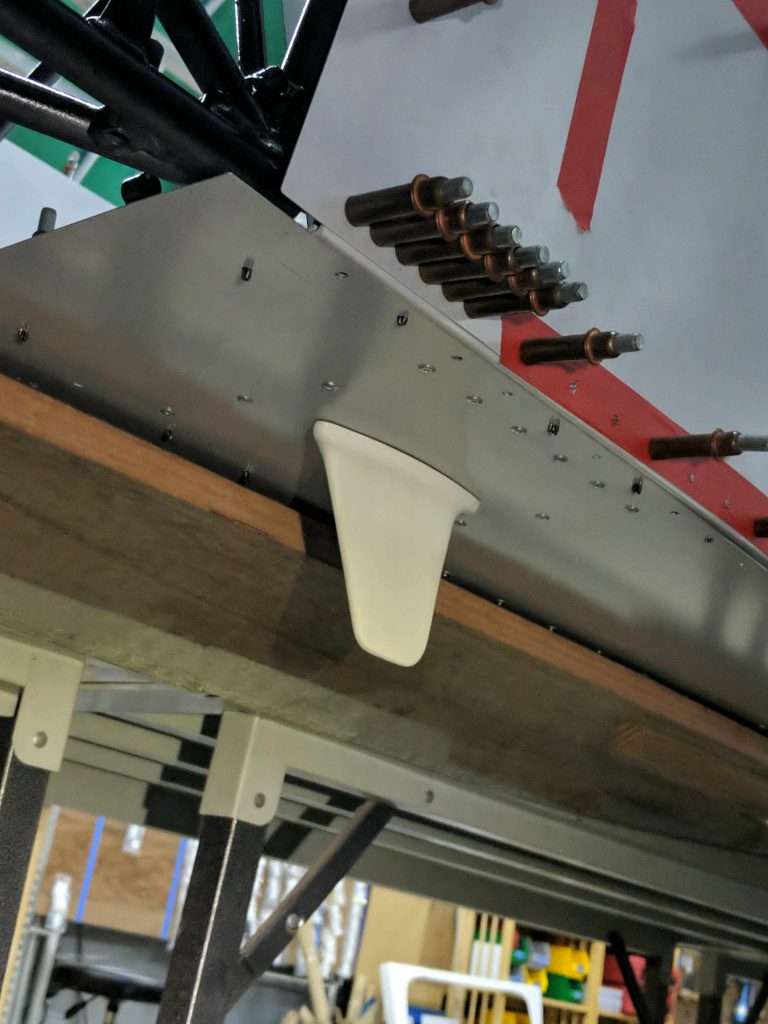
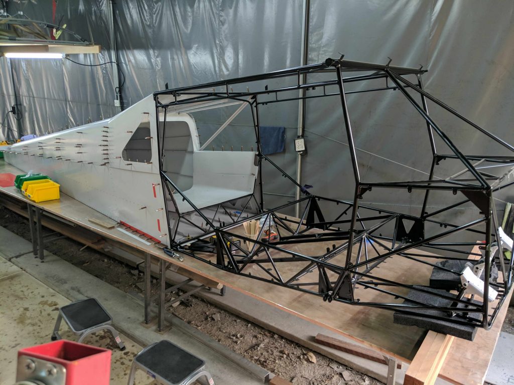
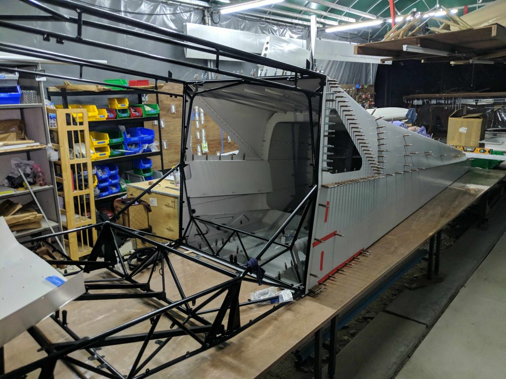
Then it is time to start working on mating the tailcone to the cage
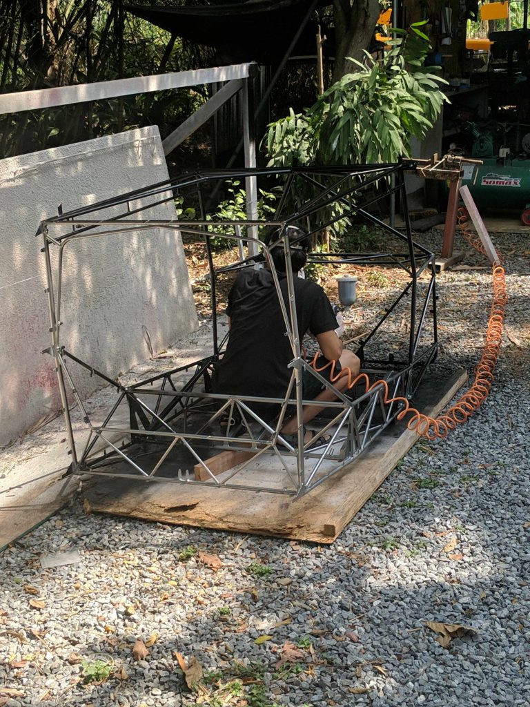
It is probably unnecessary, but I decided to try painting the powdercoated cage black to reduce any reflections or glare while flying. I’m not even sure how well the paint will stick to the powdercoat. I might regret this later…
Then after a lot of measuring and leveling and adjusting, once we get the tailcone perfectly aligned with the cage, at the right angles and with twist eliminated, we finally drill the longerons to mount to the cage gussets.
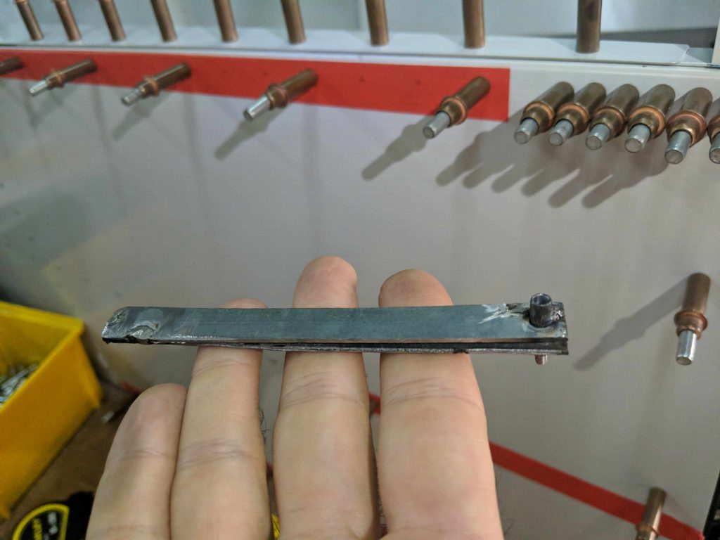
We built a little “hole finder” out of scrap steel, and nut rivet and an M3 screw. This really helps for transfer drilling a hole up to the skin piece that is covering it. This isn’t needed too often, but often enough that this tool was really useful. You simply slip the skin between the two pieces of steel in the “hole finder”, slide the M3 screw into the hole we want to “transfer up”, and then drill the skin through the nut rivet. Since the nut rivet is perfectly aligned with the M3 screw, this transfers the hole. It is easy to mess this up a bit, though, so we normally drill a smaller hole first, remove the hole finder, check the alignment, and upsize as needed.
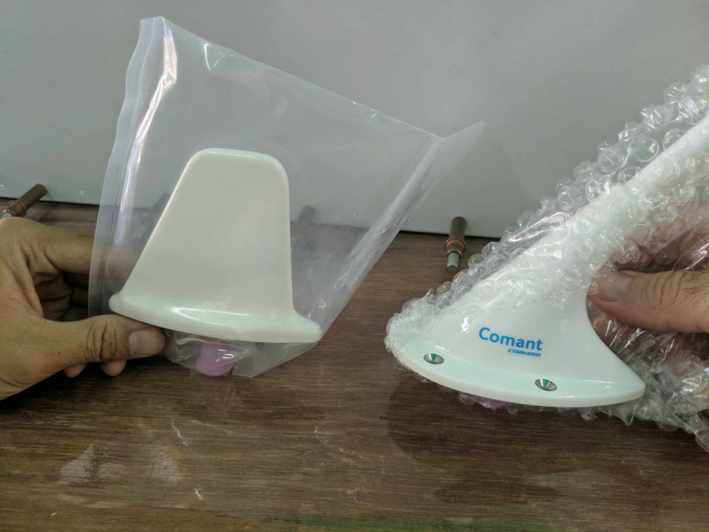
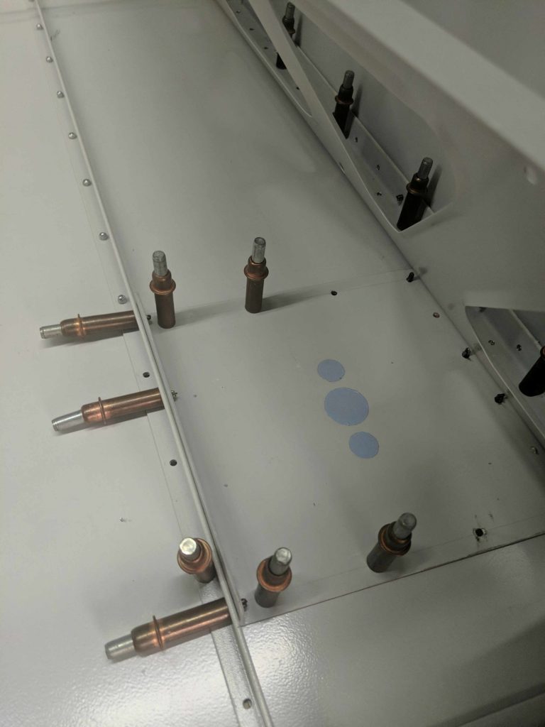
The transponder and communications antennas have arrived, so we figure it is a good time to build the antenna doubler plate on the lower side of the tailcone near the cage.
We start by sanding out the primer where the doubler needs to make an electrical connection to the tailcone skin. This is necessary because the antenna needs a ground plane, and the entire tailcone makes for a much bigger groundplane than just the doubler. The tape marks where the extents of the doubler will be, from stringer to longeron, providing a good amount of structural support to the antenna when flying at high speeds.
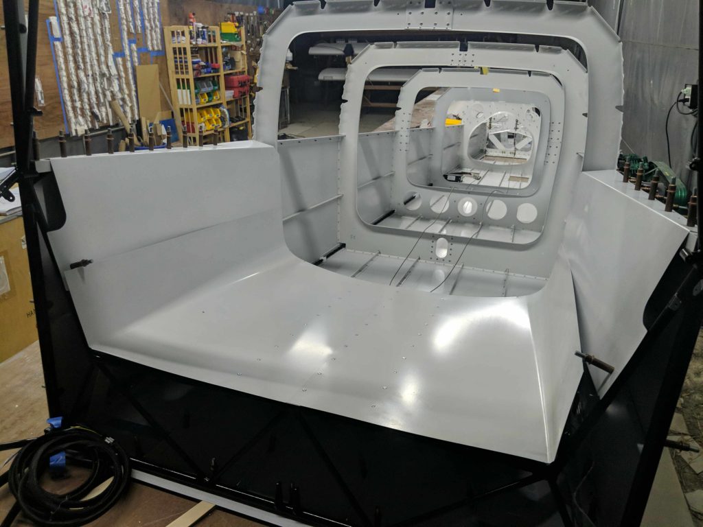
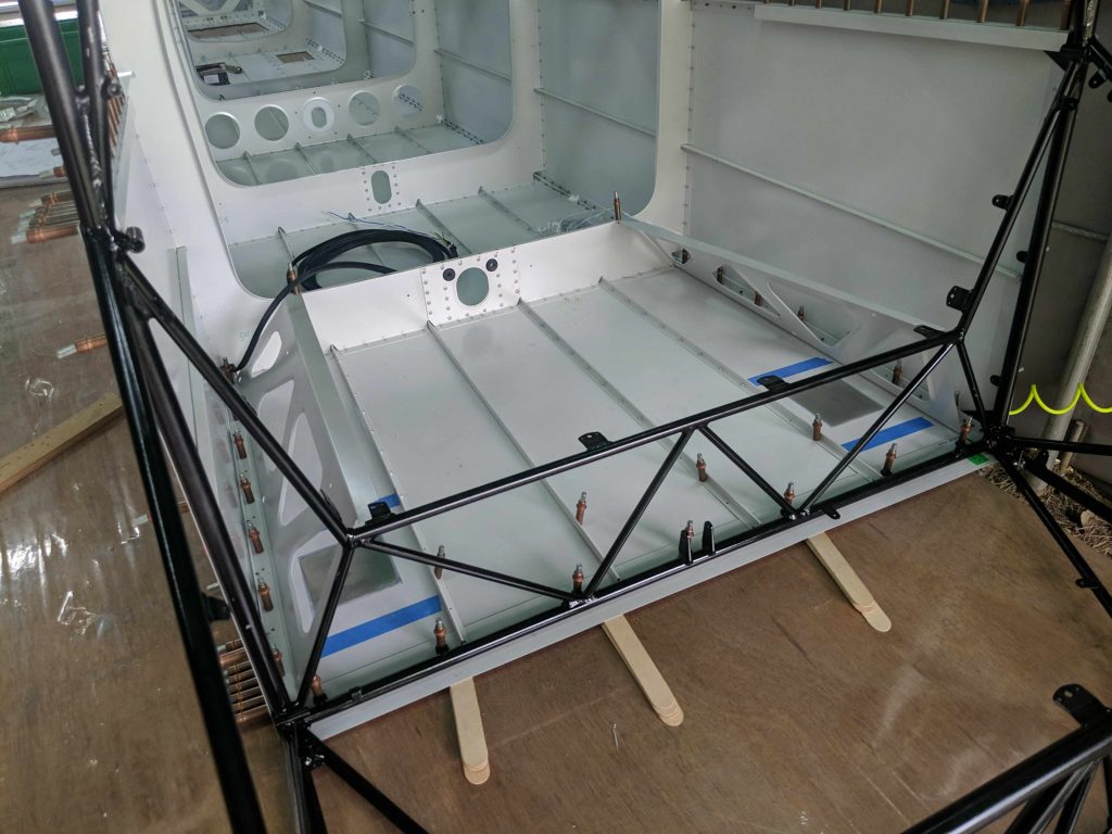
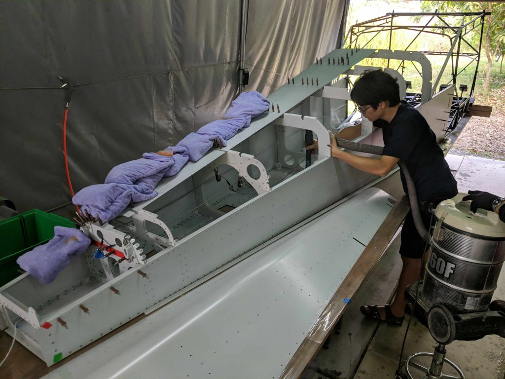
Then we start working on the aft baggage area.
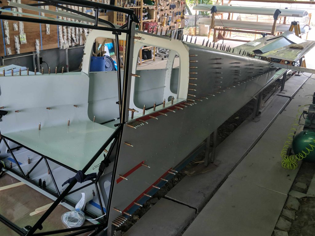
At this point we are ready to add the tailcone top skins.
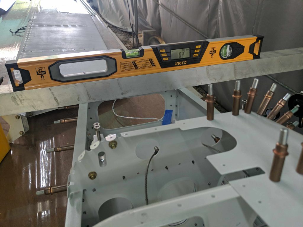
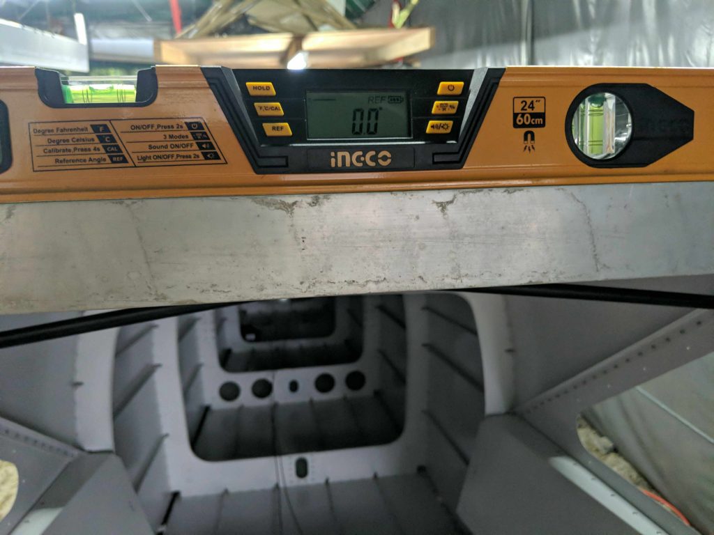
It is important not to introduce any twist over the next few steps, so we put a straight aluminum bar across both the end of the tailcone and the top of the cage and repeatedly check the angle for any twist.
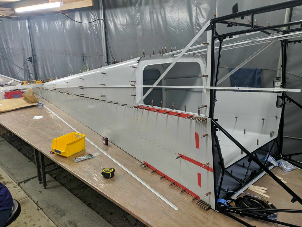
The other tailcone topskin Clecos on and it is time to measure the stringers to cut them to length.
At this point everything is Clecod but not riveted.
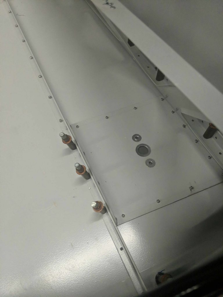
The transponder antenna doubler plate is finished and primered. The three circles in the middle are tape that blocks the primer around the antenna screw holes and connector in order to make an electrical bond with the bare aluminum when it mounts.
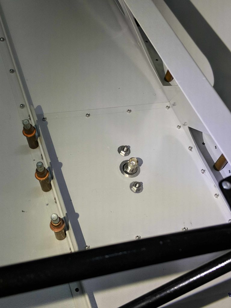
The antenna test mount looks pretty good.
On the right side is a second doubler plate in place but unused. If we ever want a second COM antenna, this is probably where it will go, but the primary COM will be on the top of the fuselage.
Next we Cleco the right top front skin in place on the tailcone.
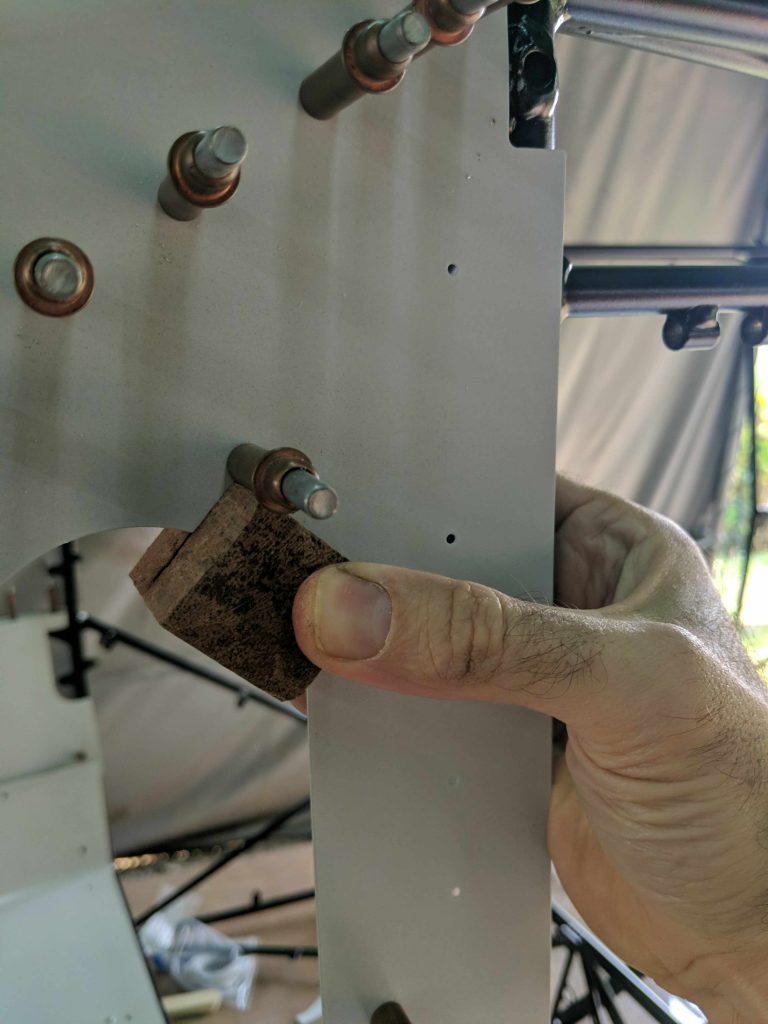
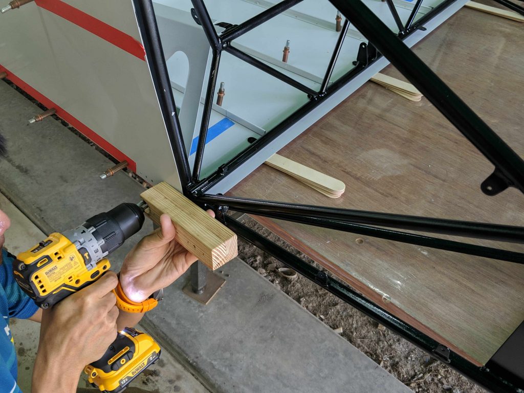
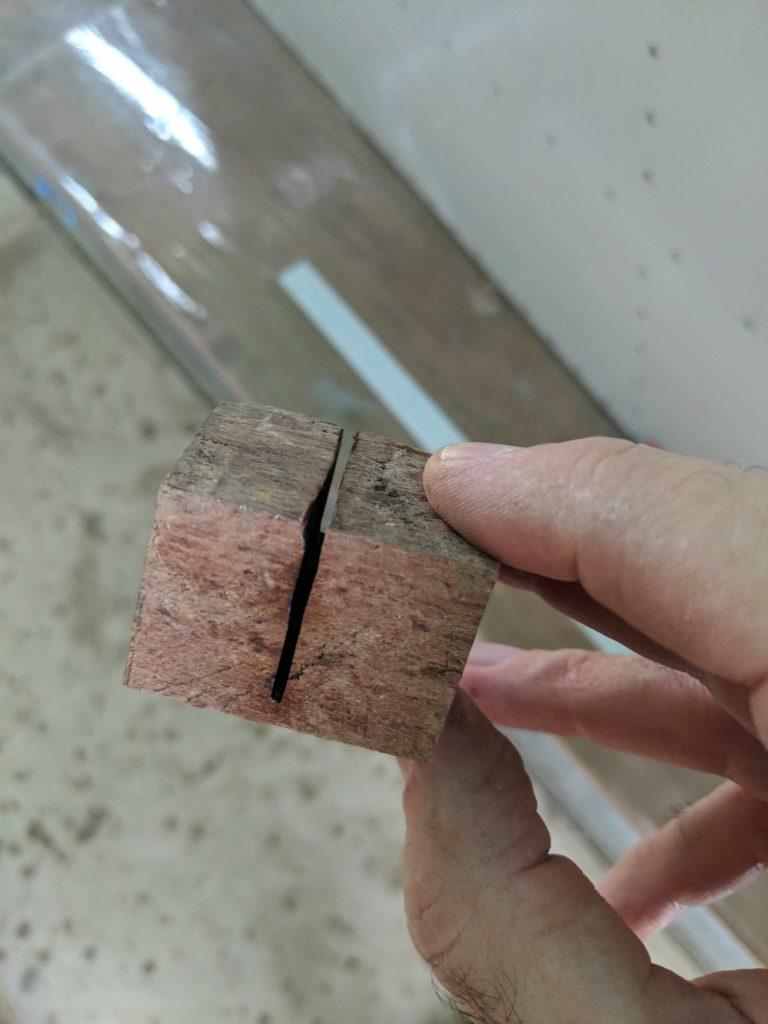
In order to clamp the skin to the cage to provide the recommended tension while transfer drilling, we cut a slot in this little scrap wood to grab the skin and have a place to mount the clamp.
Front topskin transfer drilling complete
Same thing on the other side

And the tailcone is basically complete (with Clecos, not yet riveted)
Then it is time for a final removal of the top skins, and debur all the holes that were transfer drilled before final riveting of the tailcone. We use small sandbags to hold the fuselage down to maintain zero twist for each step.
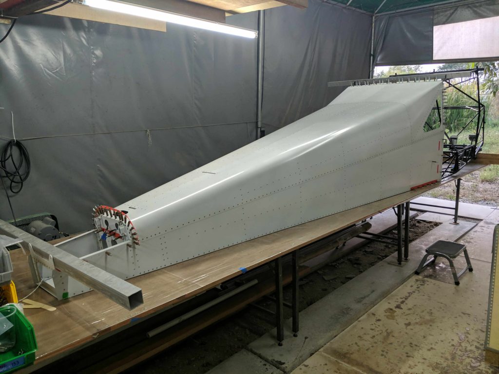
Everything is reassembled and final riveted.
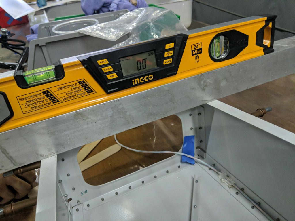
With sandbags removed, tailcone and cage twist angle is less than 0.1 degrees! Better than I expected.