In this post, I will demonstrate one of my earliest experiments in using SPICE for simulating a zener diode. In my previous post, I talked about my history with power electronics and how I am beginning to use circuit simulation to get a better handle on what is going on.
First off, I am using ngspice. Here is all you need to do to install ngspice on Ubuntu 14.04:
(from a terminal)
sudo apt-get install ngspice ngspice-doc
Fortunately for us, ngspice is in the Ubuntu multiverse repo.
Now to run it, you need to save this to a file called zener.cir:
Simple zener diode test
*
* A simple zener diode test circuit
*
vin vcc gnd SIN(0v 24v 50Hz)
dbridge mid vcc DMOD
rload mid gnd 100
*
.model DMOD D(bv=12v)
*
.end
ngspice zener.cir
and then from the ngspice prompt, type:
run
plot v(vcc,mid) vcc
If you’ve done all of the above steps properly, you should now see a window with the following plot:
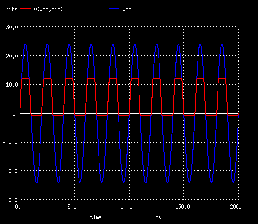
You can see the diode reverse voltage (vcc->mid) in red, and the vcc sinusoidal voltage of the power supply in blue. Notice how the diode voltage breaks down at 12V. To plot the voltage across the resistor you could do:
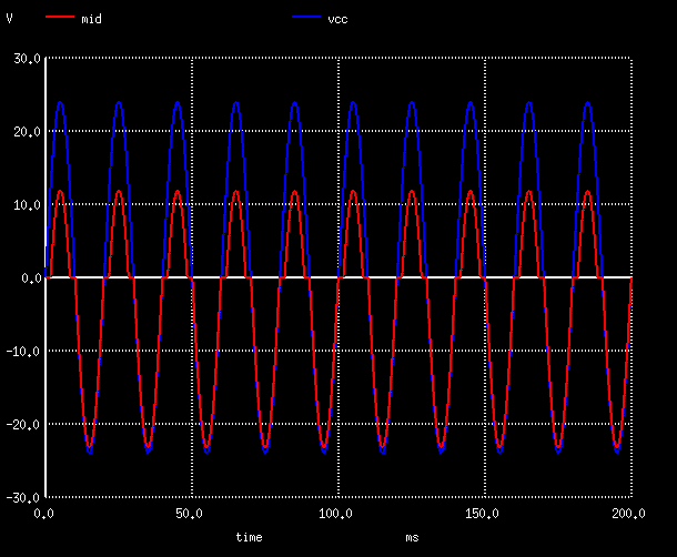
plot mid vcc
This results in the following plot:
Now feel free to tinker with the file and make adjustments. Once you’ve made your changes and saved it, you don’t need to re-run from the beginning. Just type something like the following:
source zener.cir ; run; plot v(vcc,mid) vcc
As one final note, there is a trick I’ve seen in many places to measure current. Basically, since power supplies in ngspice allow you to measure their voltage as well as current, you can create a 0V power supply anywhere in your circuit and use it to measure current. Here is a modified version of the above with a 0V power supply called “vmeas” bewteen “vin” and “dbridge”:
Simple zener diode test
*
* A simple zener diode test circuit
*
.tran 10us .2s
*
vin vcc gnd SIN(0v 24v 50Hz)
vmeas vcc top 0V
dbridge mid top DMOD
rload mid gnd 100
*
.model DMOD D(bv=12v)
*
.end
Make the changes to your file, save it back out (to the same filename zener.cir) and now you can use the following commands to reload and plot the current:
source zener.cir ; run
plot i(vmeas)
That’s it.
For my next post on this subject, I will try to demonstrate (my first foray into) how to use ngspice to model a MOSFET based on a datasheet.
If you try any of this out, please send me a comment to say how it worked for you!
This comment has been removed by a blog administrator.