A few months back, I saw this post from my friend Professor Montri Karnjanadecha regarding timing of an Arduino Nano pin. In it, he uses an oscilloscope to test what kind of speeds you can get from alternately pulling high/low a pin.
But as he points out, he doesn’t get as much speed as he could due to the Arduino main loop overhead.
I’ve never been a big fan of Arduino personally. I can understand why people like it, and good for them. It is a great platform to begin exploring microcontrollers. But once you have a feel for the hardware (and particularly if you have a strong background on C/C++ programming), it feels to me like it takes a bit too much control away for not so much gain.
And Montri’s post is an example of this. The fastest waveform speed he can get with digital I/O writes is ~1.1MHz using a 16MHz ATmega328.
For my test, I am running the same ATmega328p board that I am using for the “smart lights” running at 8MHz. (Bear in mind that since I am using the internal 8MHz RC oscillator and he is running with an external 16MHz crystal oscillator, I am running at half the clock speed, which means half the speed on everything.) Also, I am using the standard avr-g++ compiler installed on Ubuntu from the ‘gcc-avr’ Debian package. (“sudo apt-get install gcc-avr”)
Here is the equivalent code to what Montri wrote on Arduino using the more “bare bones” C approach:
#include <avr/io.h>
int main( void )
{
// set-up PB6 to be an output pin
DDRB |= _BV(6);
// do main loop
while(true)
{ PORTB |= _BV(6); PORTB &= ~_BV(6); }
}
avr-g++ -O2 -mmcu=atmega328p -Wall -DF_CPU=8000000
-o pin_switch_test_firmware.out
pin_switch_test_firmware.c++
-Wl,-Map=pin_switch_test_firmware.map -static
avr-objcopy -R .eeprom -O ihex
pin_switch_test_firmware.out
pin_switch_test_firmware.hex
avrdude -p m328p -P usb -c avrispv2
-U flash:w:pin_switch_test_firmware.hex
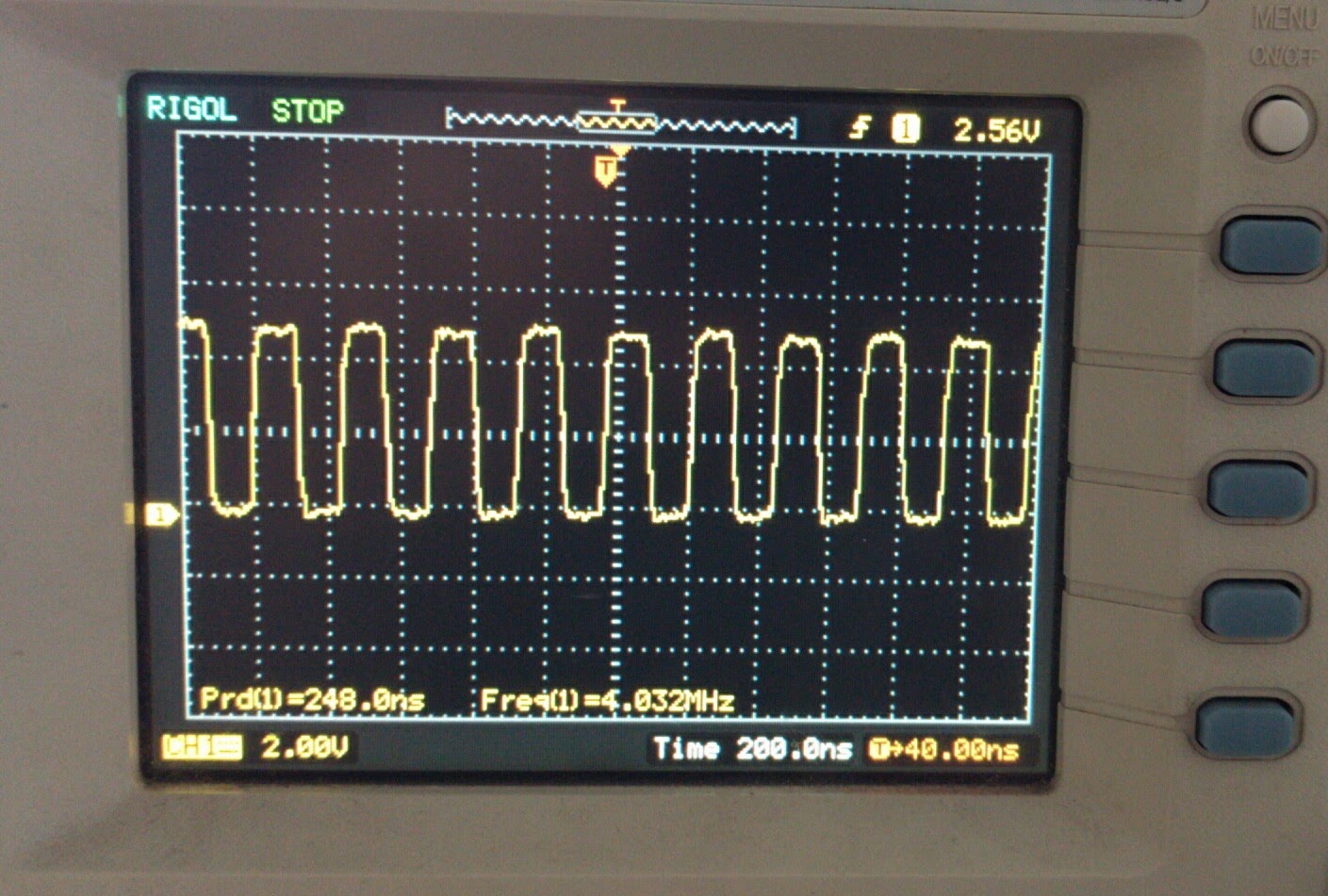
Here is a picture of the scope on this test running the above program:
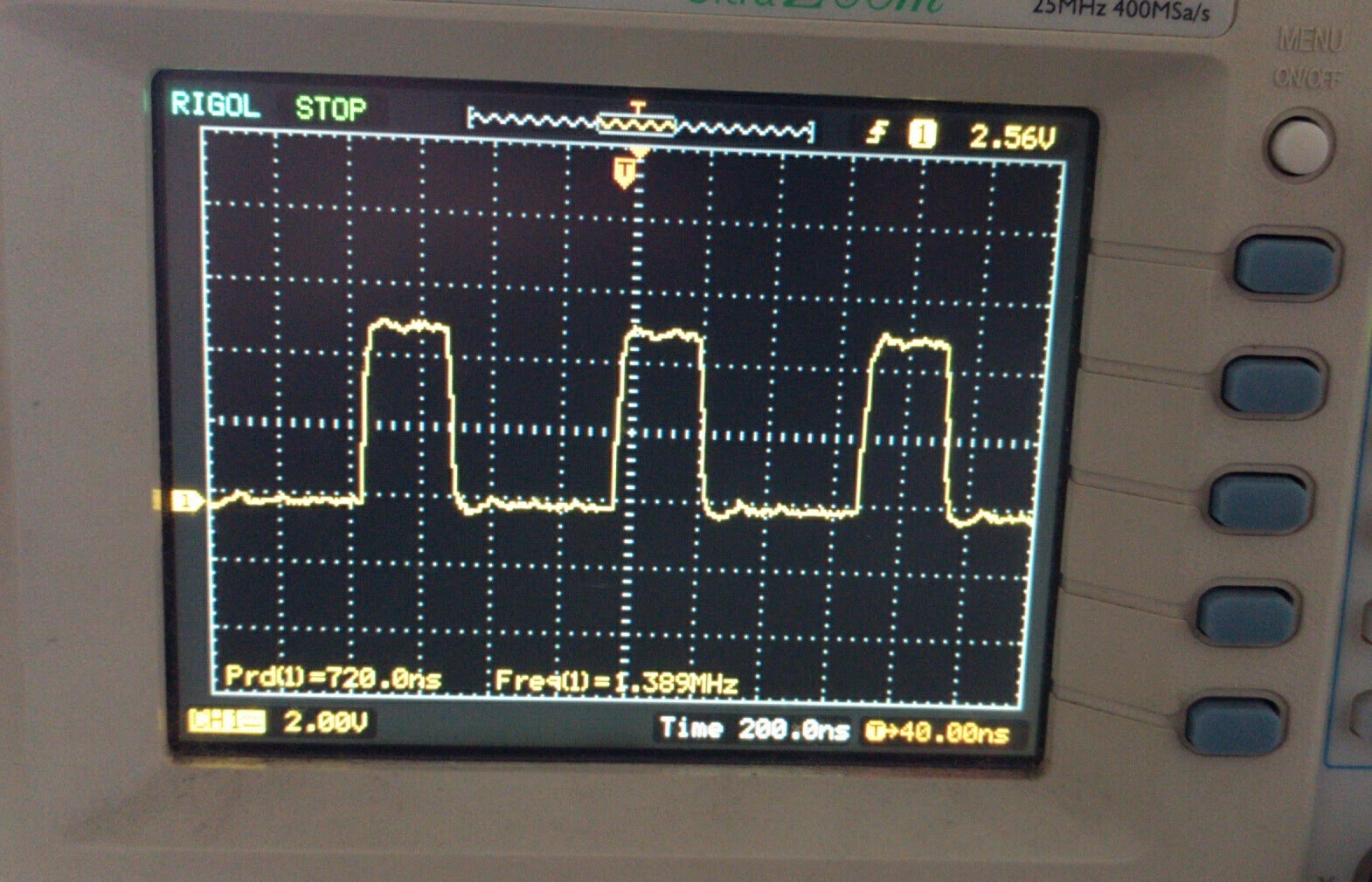
This is about a 1.4MHz waveform. Despite running at half the clock speed, it is already faster than the Arduino Nano running similar code. While it is less asymmetrical compared with Montri’s test case, you can still see how it is low longer than it is high. This is due to the “while( true )” adding time.
It can be useful to check out the assembly code created by avr-g++ to understand timing. The way to do that is to add a “-S” to the compiler:
avr-g++ -S -O2 -mmcu=atmega328p -Wall -DF_CPU=8000000
-c pin_switch_test_firmware.c++
Looking at the output assembly code file, the main function compiles to:
.L__stack_usage = 0
sbi 0x4,6
.L2:
sbi 0x5,6
cbi 0x5,6
rjmp .L2
- Take the number 6, and use the _BV() macro to turn it into the binary number b00100000 (a one in the sixth place)
- Load the value of PORTB
- OR the values from #1 and #2 above
- Store the result from #3 back into PORTB
- set bit number 6 in register 0x5 (PORTB)

#include <avr/io.h>
// timer1 constants
#define MODE_FAST_PWM_8BIT 5
#define MODE_FAST_PWM_ICR1_TOP 14
#define COM_CLEAR_ON_MATCH 2
#define CLKSLCT_CLKIO_DIV_1 1
int main( void )
{
//————————————
// enable PWM1
// set OC1A(=PB1) to be an OUTPUT pin
// and pull pin low
DDRB |= _BV(1);
PORTB &= ~_BV(1);
// set OCR1A compare output mode
TCCR1A &= ~( _BV(COM1A1) | _BV(COM1A0) );
TCCR1A |= ( COM_CLEAR_ON_MATCH << COM1A0 );
// set waveform generation mode
TCCR1A &= ~( _BV(WGM11) | _BV(WGM10) );
TCCR1B &= ~( _BV(WGM13) | _BV(WGM12) );
TCCR1A |= ( (MODE_FAST_PWM_ICR1_TOP&0x3) << WGM10 );
TCCR1B |= ( ((MODE_FAST_PWM_ICR1_TOP>>2)&0x3)
<< WGM12 );
// set timer counter to 0
TCNT1 = 0;
// set TOP
ICR1 = 1;
// set match value
OCR1A = 0;
// start the PWM clock
TCCR1B &= ~( _BV(CS12) | _BV(CS11) | _BV(CS10) );
TCCR1B |= ( CLKSLCT_CLKIO_DIV_1 << CS10 );
while( 1 );
}