First step is to pressure test the tank, which means we need to seal all the holes, including the big one up top for the fuel cap.
For the sight gauge holes, we slip on the sight gauge tube partway just to seal them
The pressure test will be very low pressure. Less than 1PSI. So a low pressure inflatable kayak pump is more suitable than a tire pump. Notice the rubber gasket we cut around the nozzle to help seal it when we pump up the pressure in the tank.
We will pump in the air via the aft fuel withdrawal hole.
During the inflation process, the tank ballooned outwards at less than 1PSI, so we placed a couple of sandbags on the tank to hold the fuel cap tape in place and several people pressed down on the top to minimize the ballooning.

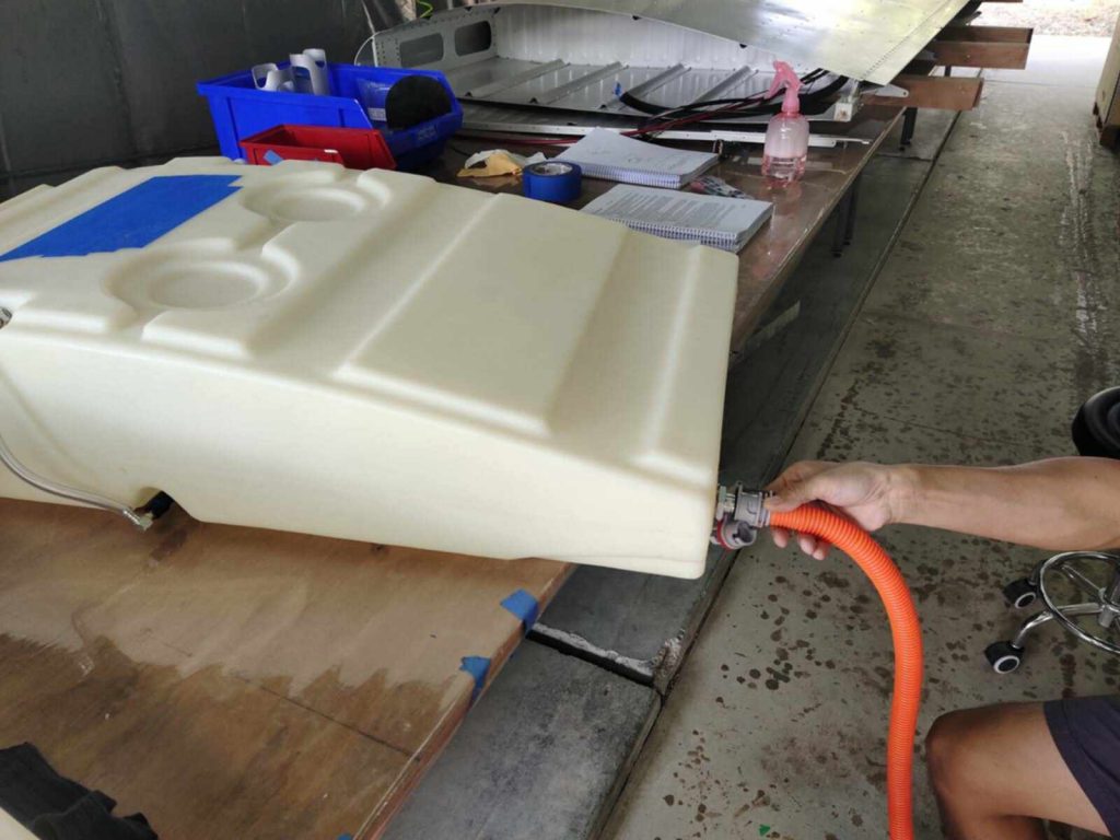
We wanted to do it quickly and be done with it quickly because we didn’t want the tanks to deform, so very few pictures from this process. (Note that a 39″ x 20″ tank has 780 roughly square inches of area top and bottom, so at 1 PSI that is 780 pounds of force on both top and bottom surfaces!)

So we quickly sprayed soapy water onto the sight gauge and aft fuel withdrawal holes with their fixtures in place and thread sealant applied to the threads (and allowed to dry almost 24 hours).
After that, the tank was inserted into the wing, and the scupper gasket was inserted from the inner root rib by pressing down on the tank and slid into place. (Our kit shipped just after Rans included this scupper in the kit, so we bought the Viton gasket material and cut it ourselves.) Since the liquid gasket is messy, we applied tape around the hole for any spillover.

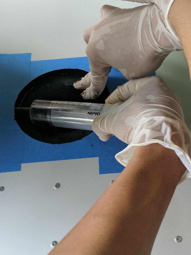
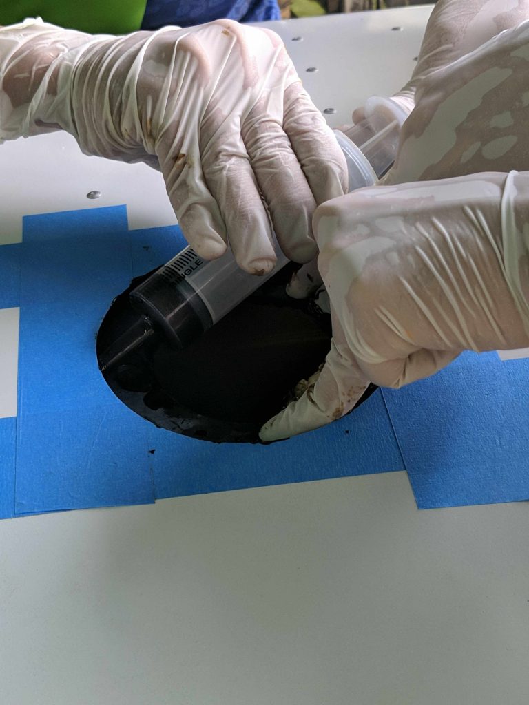
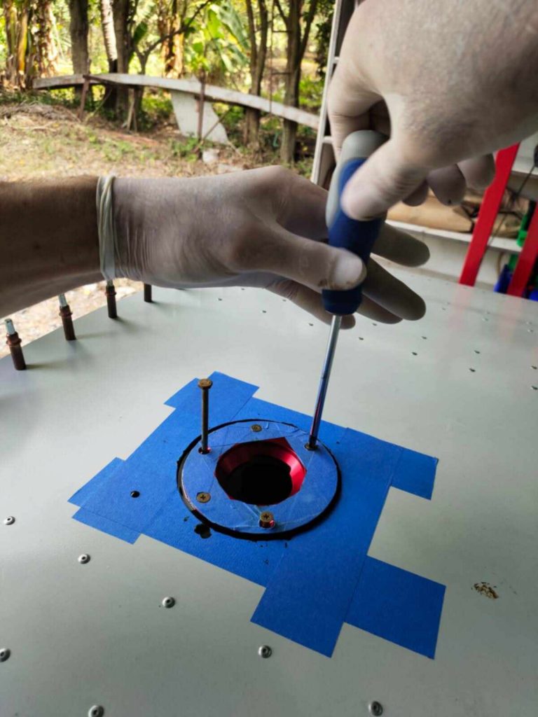
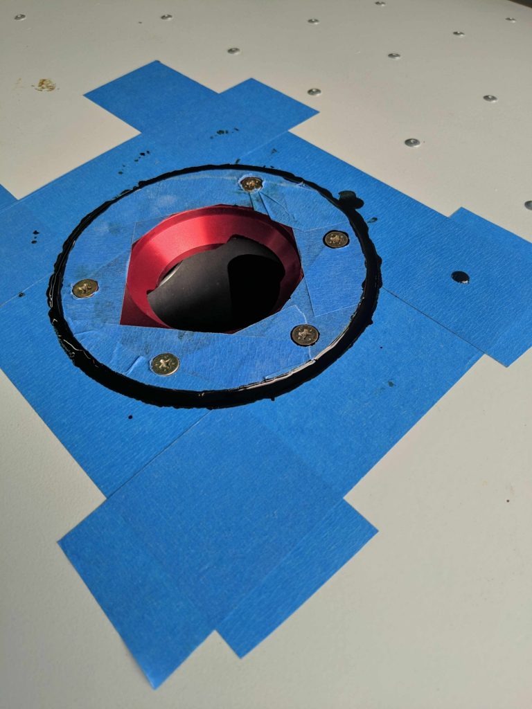
(ProSeal was very hard to source or import into Thailand, so we asked around and decided to use Permatex fuel compatible liquid gasket as that was sourceable in Thailand.)

Tape trimmed clean around fuel cap hole with scupper resting on tank

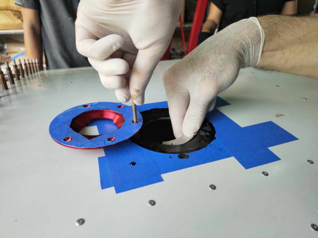
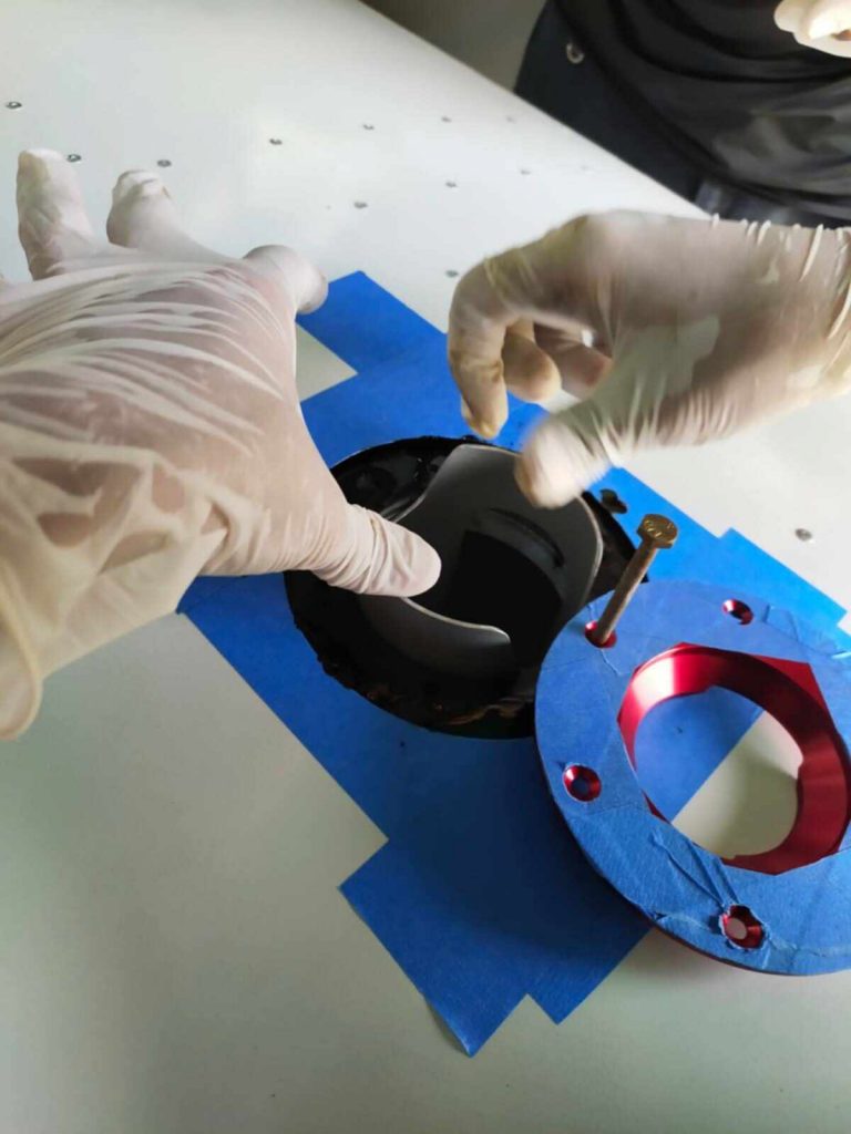
For applying the Permatex between the scupper and the fuel tank, we used two people wearing gloves to keep the stuff off our hands. (Sorry, no picture taken.) One person slides the scupper around to make different parts of the fuel tank exposed, and the other one uses a brush and tries to brush an even coat of the Permatex around the fuel cap hole and out to about 2-4cm under the wing skin.

Then we used a syringe to inject the Permatex between the wing skin and the scupper
An extra pair of hands is helpful to push the top of the fuel tank down while applying the Permatex with the syringe
Things are messy now with the wet liquid gasket everywhere, but we try to avoid messes when slipping the fuel cap inner support ring into the hole (which is C shaped to get it in), and then use a long 3/16″ bolt to screw one hole in through the fuel cap outer ring, scupper, fuel tank, and the inner support ring.
Once the bolt is in, everything is held in place while we slide the fuel tank support in through the 3″ hole with the outer fuel cap ring out of the way. (Note to anyone preparing to do this: make sure the 3″ hole you cut is large enough for the fuel tank support to pass through. The fuel tank support is 3″, so the 3″ hole needs to be enlarged slightly to let it through. Good thing we tested it before hand!)
Then the fuel cap ring is pivoted back and the screws are screwed in to hold it tightly while the Permatex dries
Finally, we syringed another round of the Permatex around the gap between fuel cap and wing skin to fill in the slight gap left.
The fuel tank is installed, but we will let the Permatex dry for a day before applying thread sealant to the fuel cap screws (one at a time) and removing the masking tape.