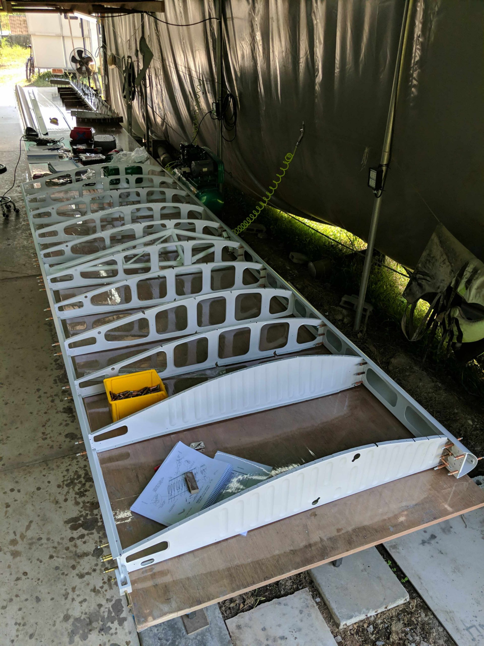
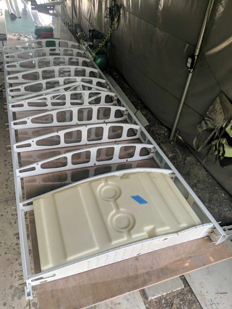
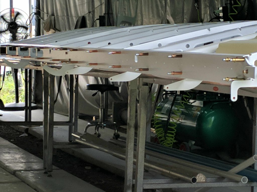
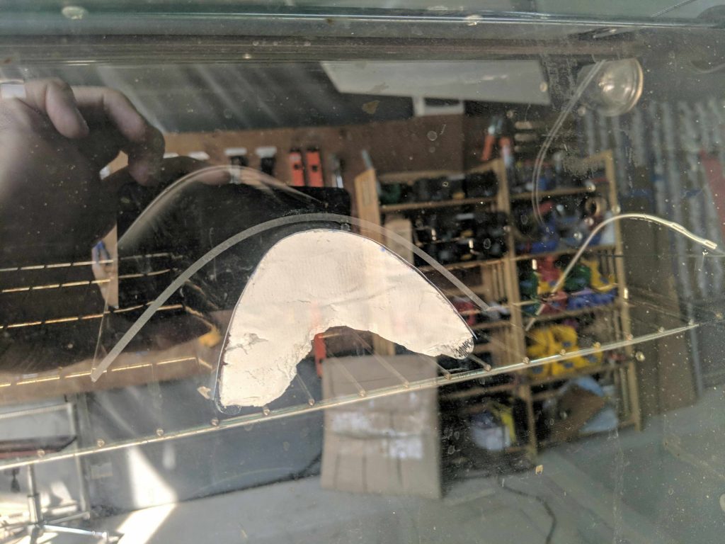
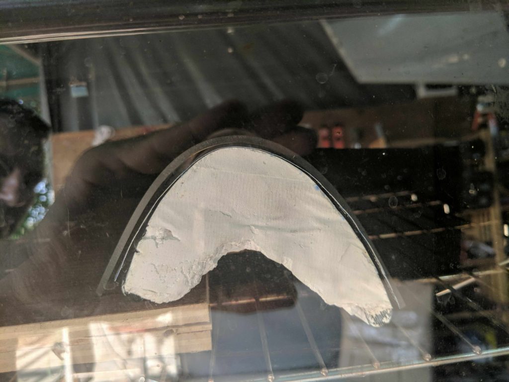
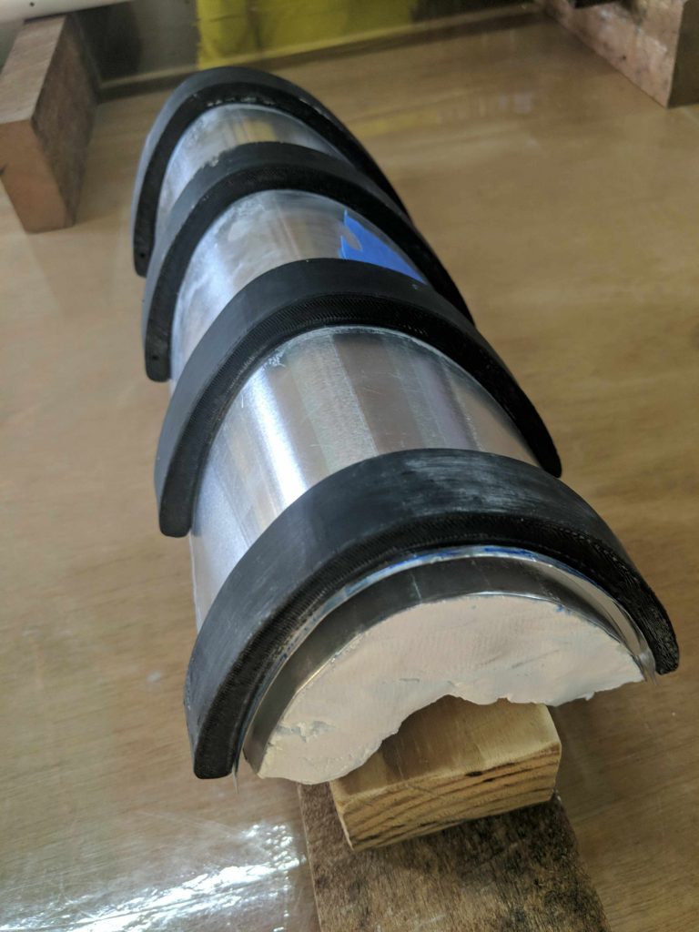
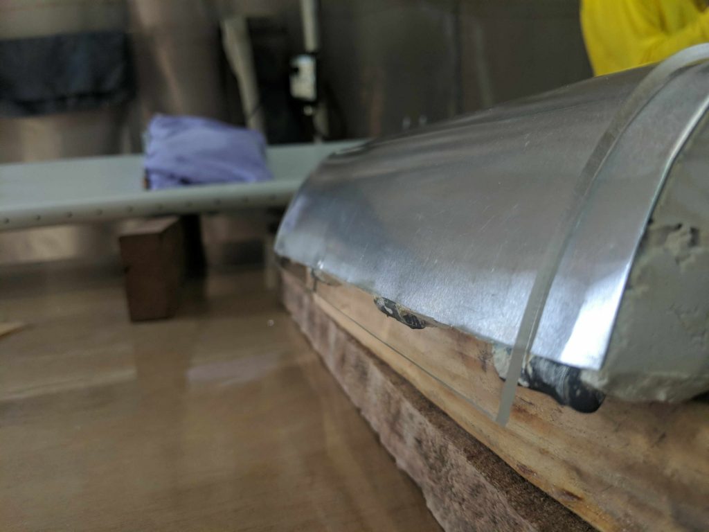
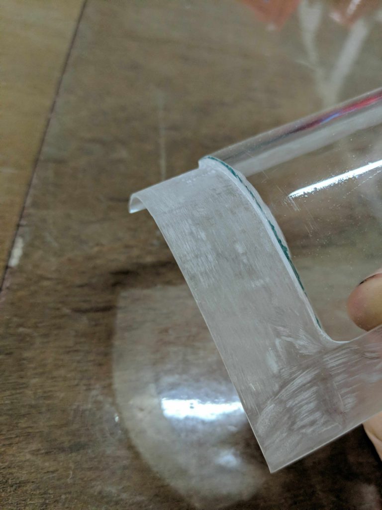
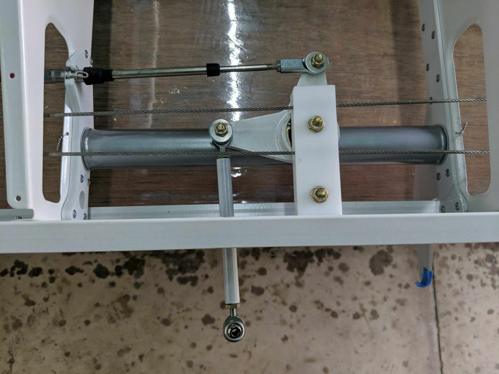
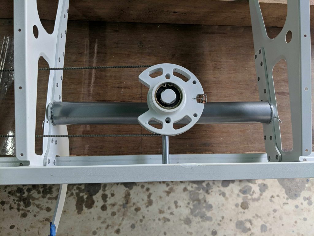
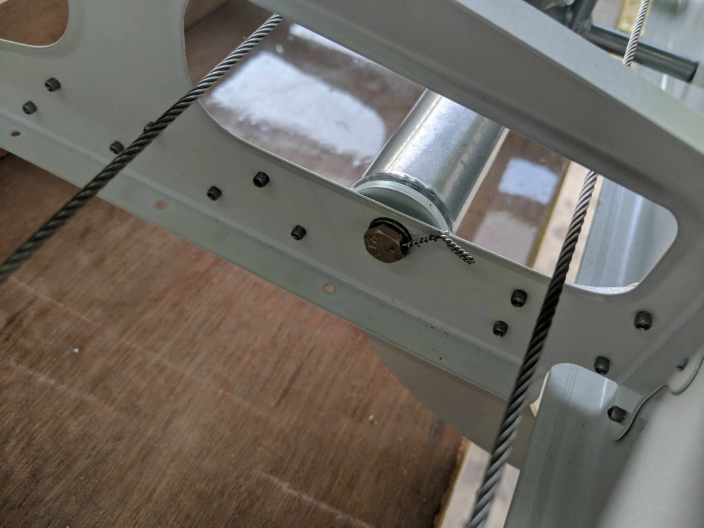
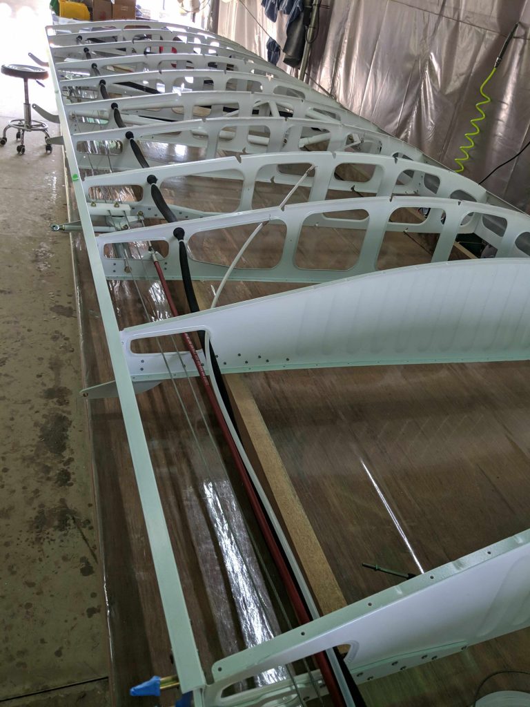
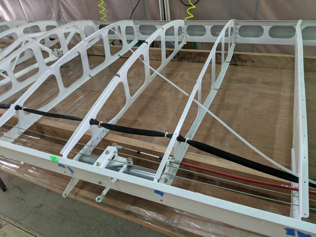
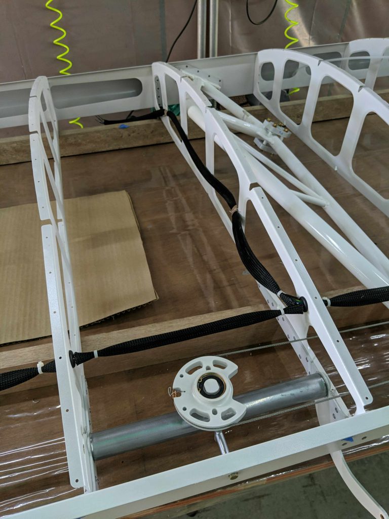
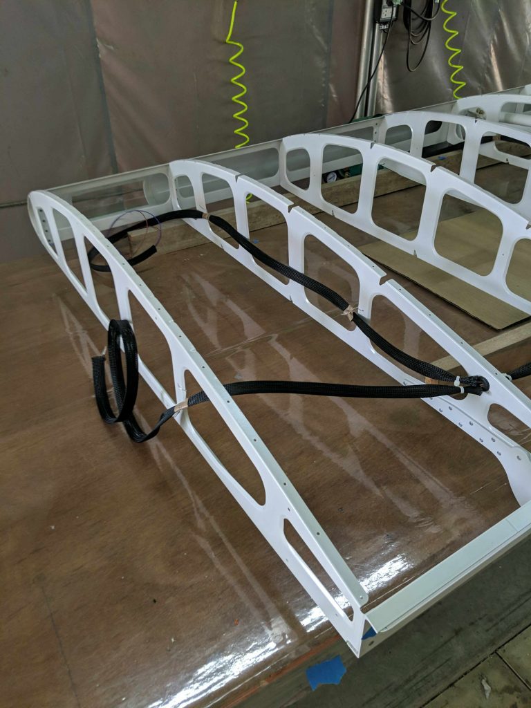
For building the wing, we are start with the frame assembly and make sure everything is good before skinning.

First we Cleco everything together (fuel tank added just for getting a sense of placement)
Assembled the flap and aileron bellcranks
We built these wooden frames for supporting the skin pieces for primer. Currently has only the stringers hanging up
Flap and aileron hinges Clecoed in place
In order to add landing lights, I decided to build my own acrylic cover to mount it in the spar. This picture gives me a spar cross-section reference to import into a CAD program and 3D print a mold for bending the acrylic
Mark out the part of the spar tip to cut out for the landing lights
A brand new hole in the spar
Baking 3mm acrylic in the oven over the mold (filled with plaster of Paris and covered in aluminum)
Acrylic has fully bent to shape
Squeeze between positive and negative molds until it cools
Worked pretty well
Cut to size and then grind to 1mm outside the hole to create a “snap lock” mount
After a few iterations of carefully grinding to size, it snaps into place quite snugly
and the light mounting brackets double as holding it in place
View from the front (with acrylic cover removed)
Flap bellcrank installed
Aileron bellcrank installed
Safety wire on the bolts holding in the bellcranks
Pitot pressure tube, flap teleflex cable, aileron sling wire… and I decided to run 10 wires (only had 9 different colors). We bought Deutsh DTM connectors for strobe and NAV lights, landing lights, plus 4 wires for an auxiliary device mount for GoPro, custom sensors, etc I might want to mount later
Everything kept nice and tidy inside the wing
Pitot pressure tube held snug by safety wire pinching in place Teflon abrasion protection tape
All of the wire run through loom which is cable tied in case it might slip a bit (but there really isn’t anywhere to slip to, so this is just an extra precaution)
Auxilliary port cables fork off after truss. It apparently is off to the right, but we added some of the Teflon tape underneath the aileron cable just in case it touches the truss, which it shouldn’t
Final fork between landing lights (upper right) and strobe+NAV lights (left)
10 wires with 9 colors with pins crimped and soldered (for extra connectivity) for DTM connectors

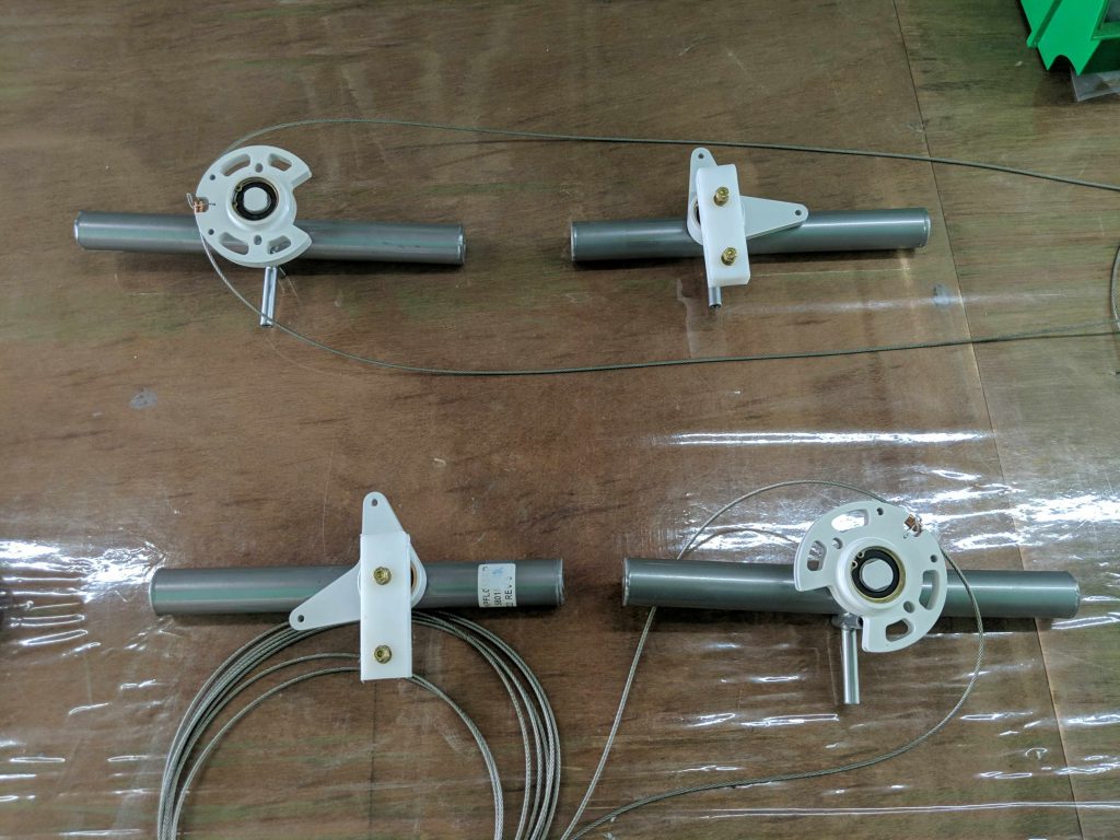
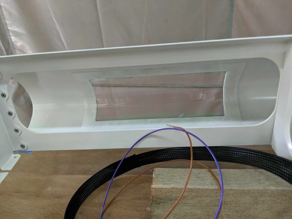
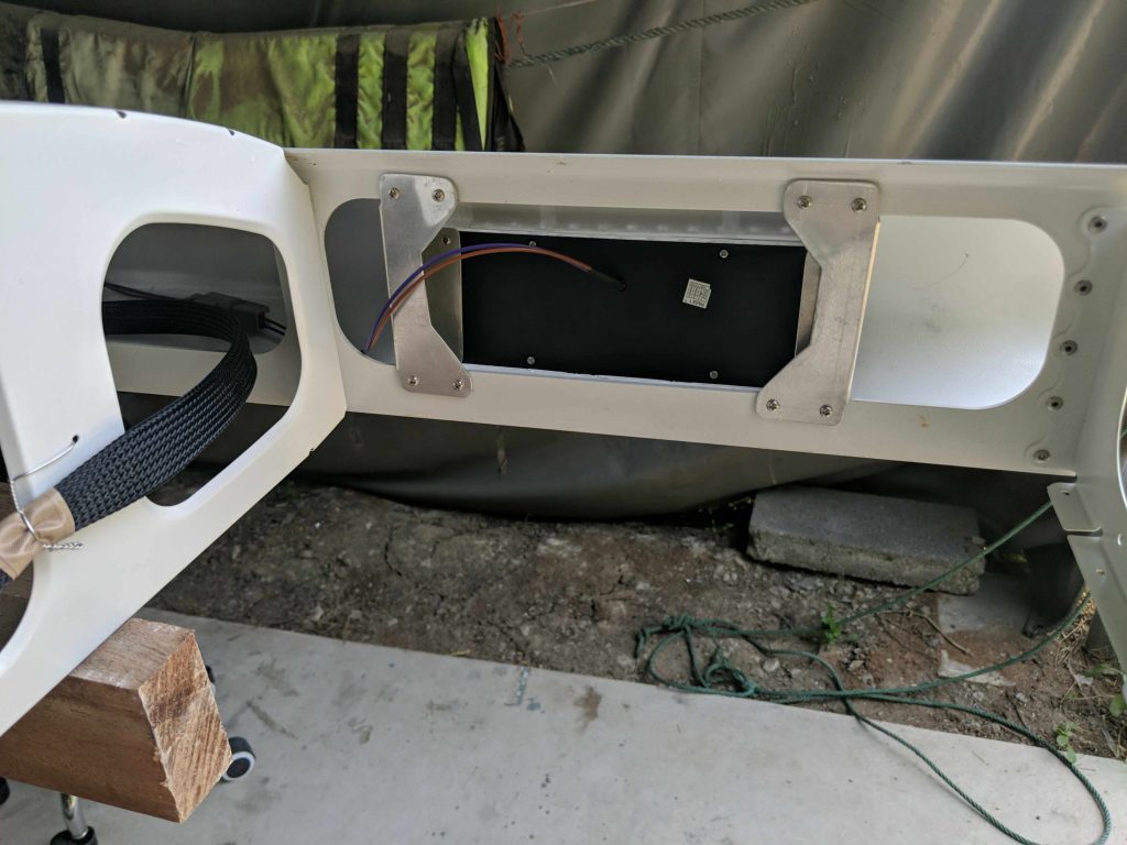
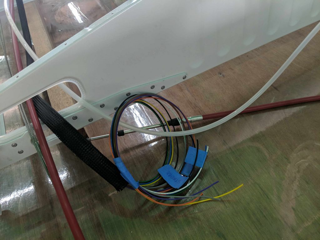
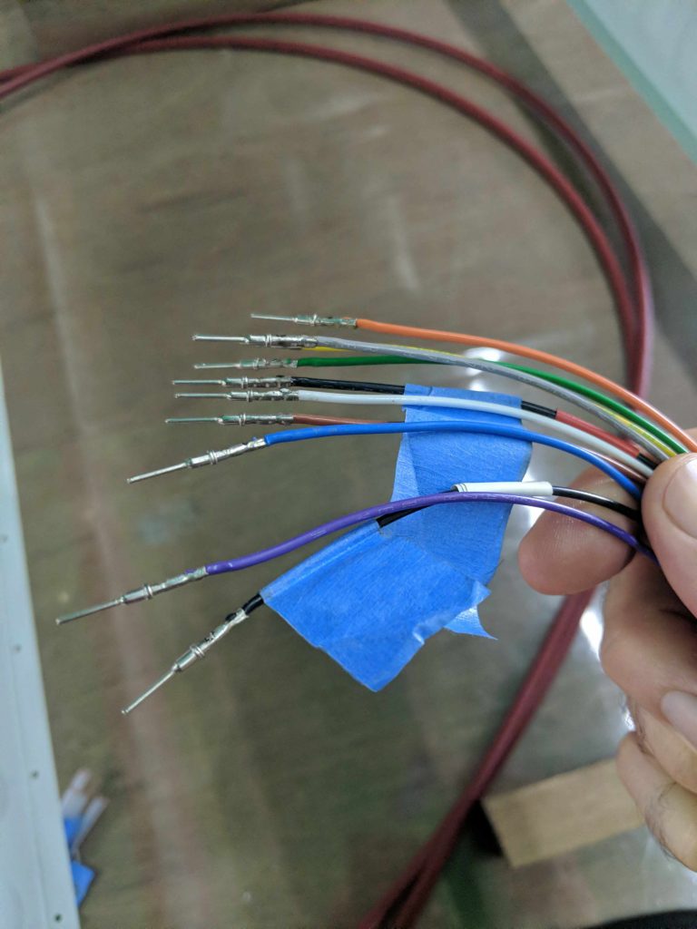
Mostly for my own reference, here is the wiring chart…
Strobe: grey(+), black with red tape(-)
NAV: orange(+), white(-)
Landing: purple(+), brown(-)
Aux port: blue(CAN-H), green(CAN-L), yellow(+), black with white tape(-)

Example of DTM connector for landing light
For the right wing, I have added 4 pitot pressure tubes for a likely experiment with dynamic,static, plus 45degs up and down to sense angle-of-attack

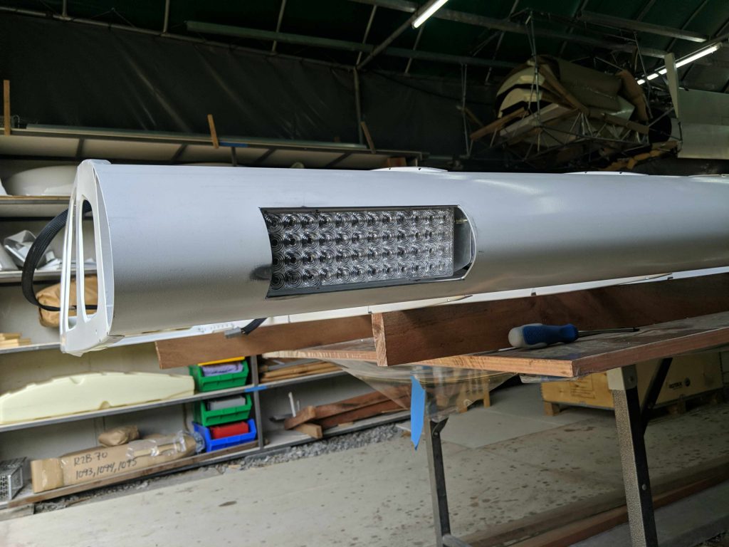
At this point we are ready for skinning, which I’ll leave for another post