We had some breakthroughs with BLDC motor drive control last week. I’ll try to summarize it here as much for my own records as for anyone else. So feel free to skip if you aren’t interested. But if you are, please read on. In particular, I came up with a very easy way to figure out the wiring of any BLDC motor very quickly and painlessly as long as you have an oscilloscope that can show at least 3 channels of the logic analyzer simultaneously with at least 2 channels of the drive.
But first some background…
After seeing some strange high frequency noise in the BLDC motor drive, we realized that the lengths of the three Hall sensor pulses were different:
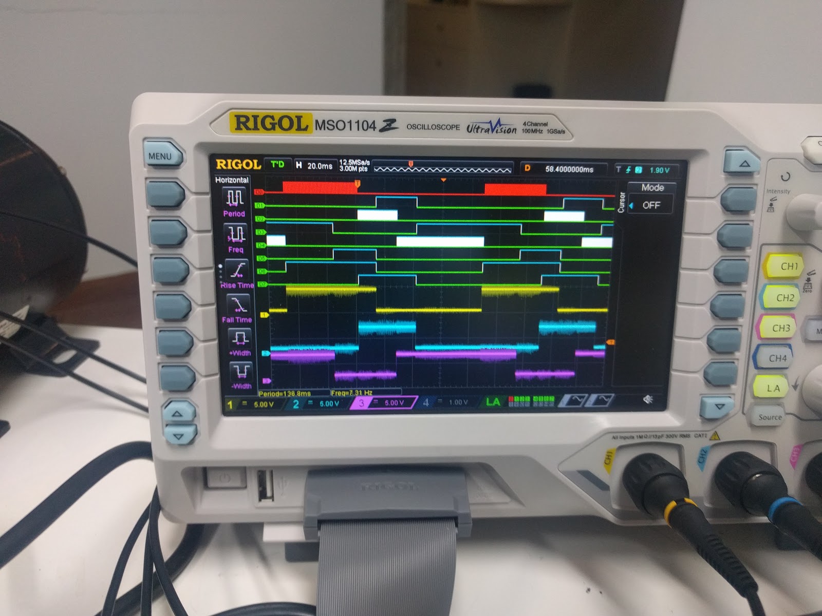
This was captured while driving at low speed and you can clearly see how the cyan (channel 2) Hall sensor is shorter than the other two (yellow/channel 1 and magenta/channel 3). The most likely explanation for this seemed to be that we had the wiring in the wrong order. Which is strange since the motor drive has wires for the U,V,W phases of the motor that are the same color as the Hall sensor wires, so we assumed that the Hall A (sometimes called U) was the wire that was the same color as the drive wire for phase U. This clarity of wiring color was the reason we switched over to this 800W motor from the 400W motor we painstakingly calculated which Hall wire corresponded to which color. Strangely, although the 400W and 800W motors are from the same manufacturer, the 400W motor doesn’t use matching colors while the 800W motor does.
I switched over when I began testing the PWM logic, so I tried switching back to the smaller 400W BLDC motor I was originally experimenting with using the wire colors that I calculated previously. And immediately, the setup from the previous post worked flawlessly. As I sent speed control commands from the serial port, the microcontroller was able to control the speed smoothly from a very slow (about 1 rotation per second) to a quite fast, with almost no noise and no vibration at all.
At this point, we knew something strange was going on with the 800W motor. The most likely candidate was that the wiring was wrong, since the force seems to change direction over the “cyan high” part of the cycle causing it to slow down before speeding up on the other parts. My guess now is that maybe which commutation drive wire “matches” which Hall sensor depends on how you define your commutation table.
Ours is defined by “set the phase U drive wire high as soon as the Hall A goes high, set the phase U drive wire low as soon as the Hall A goes low”, and similarly for the V/B and W/C phase/Hall wires. This seems like an obvious definition of “match” in that they go high and low together. And since exactly one wire is high and exactly one wire is low at any given time (while the third one is “floating”), this completely determines the commutation table. But maybe there are other ways to define it such that they are “matched” to a different Hall sensor. (In other words, to define “match” differently.) I don’t know. But it sure is weird.
Did the manufacturer just screw up the color coding? Or did they do it on purpose so that we give up and buy their motor drive controllers? Am I getting too cynical?
So now that we knew for sure we have everything right on the control logic and the wiring for the 400W motor, we used this to create a quick way to figure out the wiring of any other motor.
Here is how it works…
Since we had the motor running with our PWM drive controller, we marked which direction we were calling “forward” according to the commutation table description above. (For the record, “reverse” appears to simply be to apply the commutation table 180 degrees out of phase. I can explain this more if any of you want to know.)

We connected up the three Hall sensors to the first three channels of the logic analyzer. Then we connected channel 1 of the analog probes (in my case “yellow”) to the phase V drive wire, and channel 2 (“cyan”) to the phase W drive wire. For this test, we won’t be plugging in the power for the motor drive, which is good because we are going to need to ground to both the phase U drive wire and the ground on the Hall sensors, which we normally electrically isolate. If your scope has isolated probes, you might be able to use those instead. But we don’t have any isolated probes anymore. (Not sure why… we used to a number of years back. I can’t remember, but they might have failed a few years ago. Probably time to pick up some more.)
So the analog ground wire on the scope is clipped to the phase U drive wire, and the digital ground wire on the scope is connected to the Hall sensor ground. Now we can see on the scope “V-U” in the yellow channel, “W-U” in the cyan channel, and the three Hall sensors all at the same time.
Here is a photo of the screen when I rotated the axle of the motor in the “forward” direction half a turn using a pair of vice-grips:
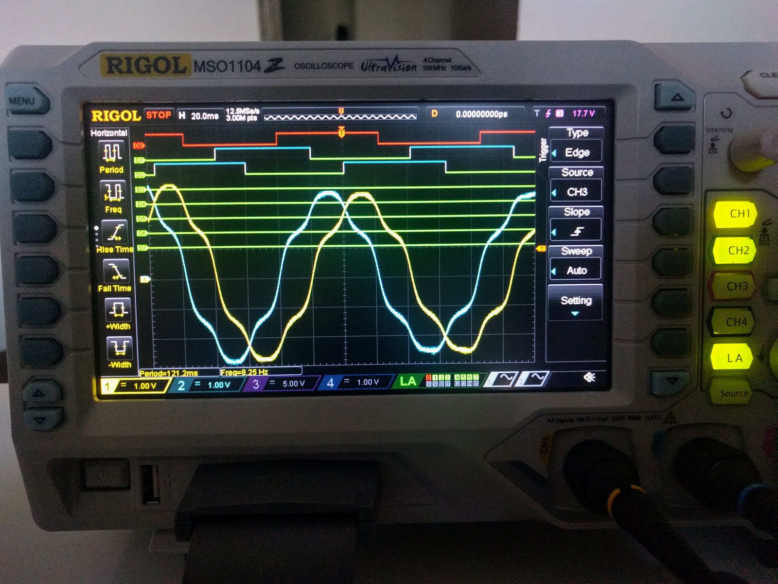
The analog channels are showing the back EMF voltage signals of the motor compared with the Hall readings. In particular, notice the following four things:
- The V-U channel is trailing (to the right of) the W-U channel.
- The middle of the “high” of the Hall A channel synchronizes to the middle of the “high” of the “W-U” channel.
- The middle of the “low” of the Hall B channel synchronizes to the middle of the “high” of the “V-U” channel.
- The rising edge of Hall C synchronizes to the point at which the “V-U” and “W-U” signals cross with positive voltage. (I.e. when they are both high.)


(In this plot, the bottom three logic analyzer channels are the Hall sensors. The top two are high/low drive channels for the U half-bridge the next two are for the V half bridge and the next two are for the W half-bridge.)
Notice how all three hall sensors are evenly spaced. But in order to see the “U-high rises when Hall A rises”, you have to read it from right to left. If you imagine going from right to left, you can see how the first channel at the top (U-high) will go high when Hall A goes high. But read from left to right, this means that the U-high channel goes low when the Hall A goes low.
So that is it. Without using any information from the vendor or any wire colors, we have determined the commutation table for this motor and figured out which wire was which.
While it didn’t occur to me before, maybe the manufacturer is referring to what I am calling the “W channel” as their “U channel”. The logic being that with what I am thinking of as “reversed logic” compared to their own 400W motor, someone who was just looking at this motor for the first time and never saw the 400W motor would notice that the W-channel low-side drive rises when the Hall A side rises, and the W-channel high-side drive rises then the Hall A side falls. So maybe they call this wire “U” since it “matches with Hall A” in this sense. I’ll go back to the lab tomorrow and check if my “W” is their “U”, and similarly if my “U” is their “V”, and my “V” is their “W”. If so, I now understand why. Apparently “matches” can be defined differently. Still weird, but a bit less weird now. 🙂