Things have been going a bit slowly on building the BLDC drive circuit for the ferry boat propeller motors. Mostly this has been due to being busy with other things. But nonetheless we’ve been making slow but steady progress over the past few weeks.
One recent big help was the purchase of a new oscilloscope. The old one was a number of years old, and the logic analyzer part of it failed a while back. On top of that, it only had 2 channels, and given that the BLDC motors we are working with are 3 phase, a third channel would come in handy. So we decided to by a new four channel oscilloscope (with working logic analyzer). We stayed with the same brand, Rigol, as the one we used before since it gave us a number of years of good service before slowly losing certain functionality. And it happens to be relatively cheap compared to some of the other alternatives. They were also quite helpful to us this time. It turns out that they don’t normally sell the 4-channel units with the logic analyzer in Thailand, but the distributor imported a single unit from Singapore just for us. I feel special.
Anyway, the working logic analyzer made a big difference in trying to debug why the BLDC drive wasn’t as smooth as it certainly should be.
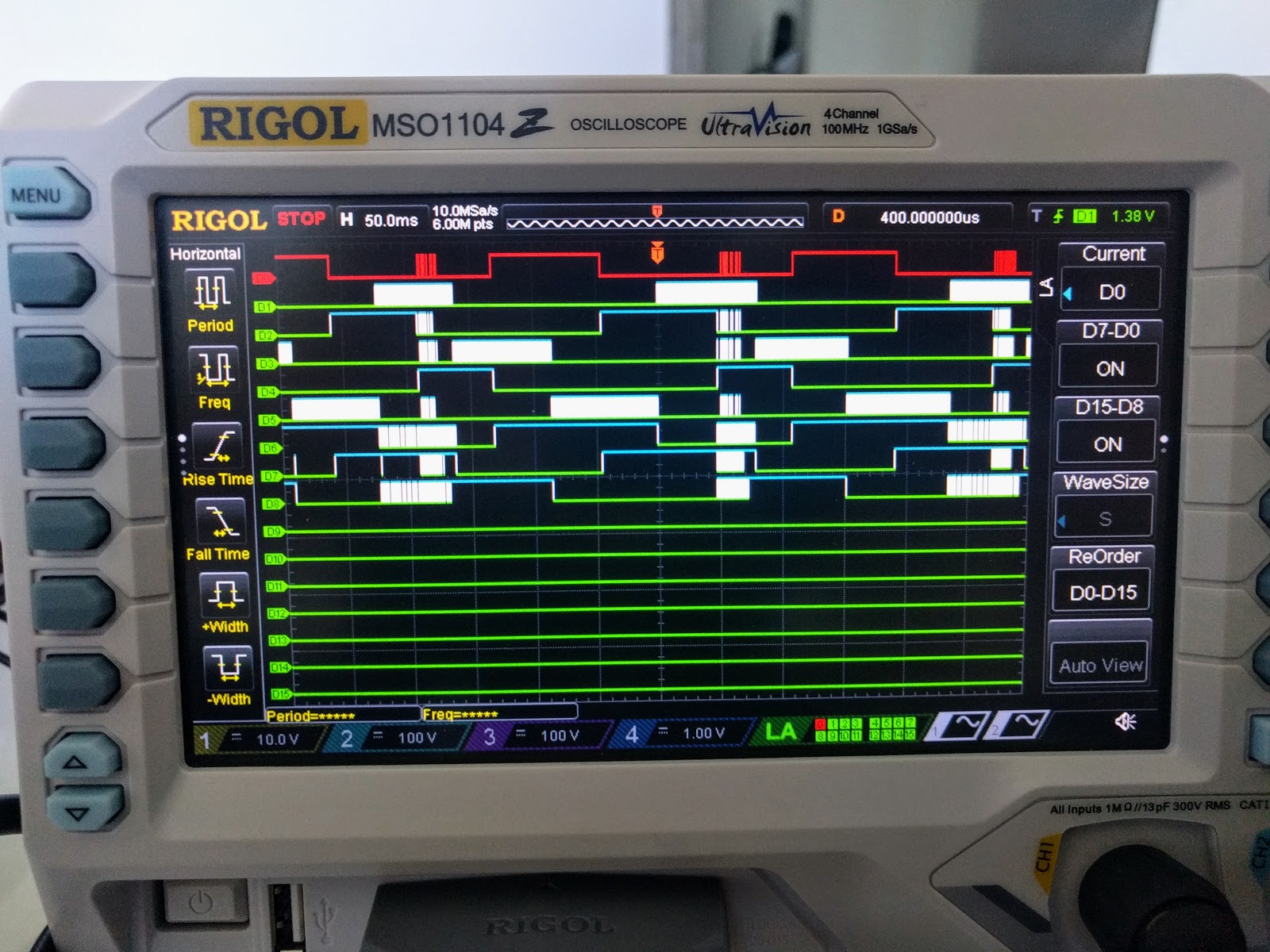
The first 6 channels are connected to the pins going to the top and bottom fet drivers for the 3 different half-bridges in the BLDC controller. The top channel (red) is the top side logic of the first (U) half-bridge and the next channel is the bottom side for the U channel. The next two are top and bottom of the V channel, with the following two as top and bottom of the W channel. The last three of the 9 active channels represent the input readings from the Hall effect sensors coming in from the motor that the controller is using to determine what the correct commutation is. (In other words the last three channels are the inputs that the controller is using to determine how to set the first 6 output channels that drive the motor.)
The second, fourth, and sixth channel are white because I am doing pulse width modulation (PWM) on those to limit motor speed. But the white on the other channels shouldn’t be there and is quite disturbing.
In particular, the bottom three channels are Hall effect sensors. They are inputs that sense the current rotation state on the motor. They shouldn’t have any high frequency noise on them somewhat correlating to the PWM signals!
Switching on the analog probes to read the Hall effect sensors on the same screen:
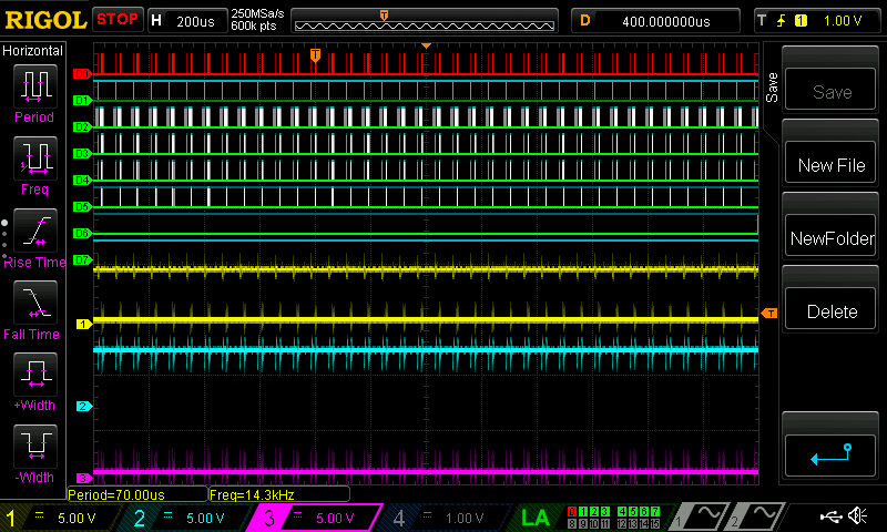
(This is saved out from the scope itself via a thumb drive.)
The yellow channel is the U Hall effect sensor, the cyan is the V, and the magenta is the W.
There appears to be some very high frequency noise in all three Hall effect channels. We checked our circuits, and the logic lines are all opto-isolated from the power lines. So my best guess now is that the EMI from the power coils in the motor is propogating through the air to the Hall effect sensor lines. I began to wonder if this simply means that we were supposed to put a low pass filter across these lines, and a quick look around the net suggests that other BLDC driver boards use capacitors just for this purpose.
So the lesson learned seems to be that we weren’t filtering out the noise on the Hall effect sensors, causing the controller to go a bit crazy and change commutation at the wrong times causing the slightly shaky drive behavior that we were seeing.
And the other lesson learned is that we caught it because we bought the instrumentation to measure it.