I got the chance to test the BLDC driver circuit that we finished recently, and after minimal fixes to the commutation code in the microcontroller, it works! I’m pretty excited about this. 🙂

Here is the setup we used:

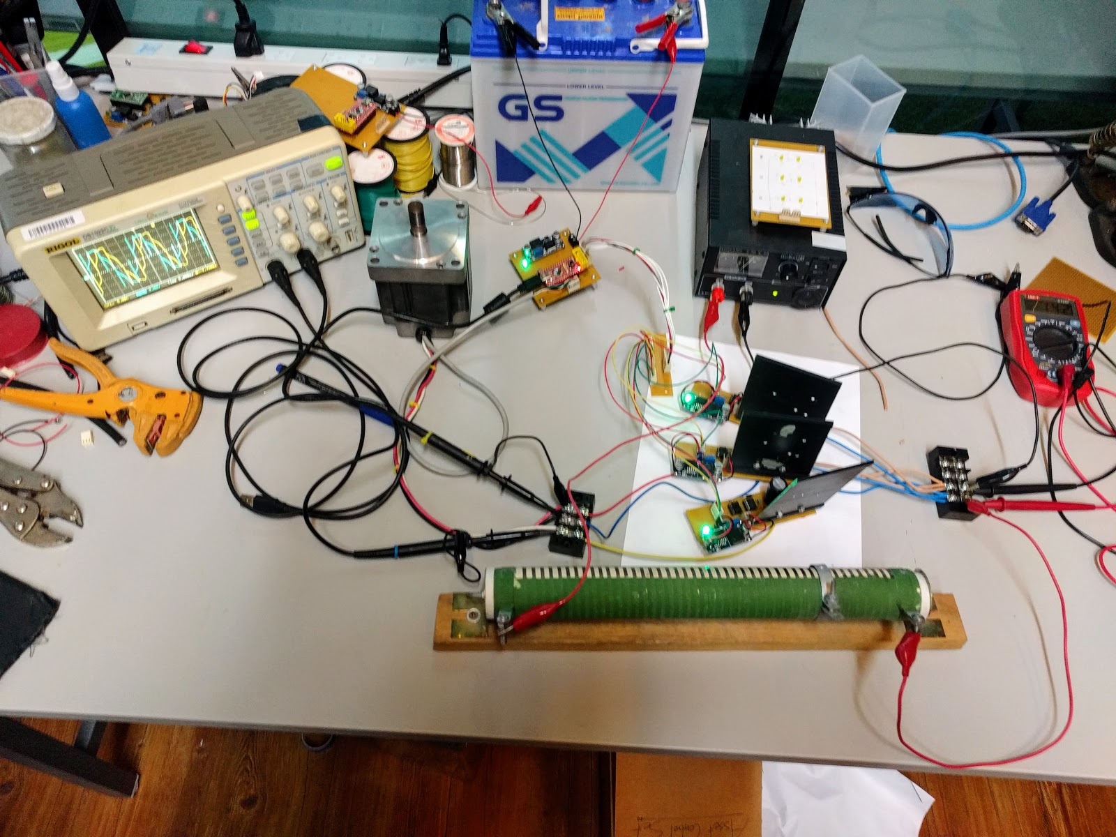
The 12V car battery at the top is supplying the power for the microcontroller which is just below it. The black box to the right is an adjustable voltage power supply. It doesn’t have current limiting, so we just ran it through a giant 10ohm high power resistor we keep around for this kind of thing (the green bar at the bottom). At 10ohms, it will limit the current to about 2 amps if we supply 20 volts on the power supply.

(My old current limiting supply blew out a number of years ago, and I just never got around to replacing it. Too many other things going on.)

Between the adjustable power supply above and the 10 ohm resistor below, you can see the three half bridge boards. (Bottom one is connected to the “U” channel, middle one is connected to the “V” channel, upper one is connected to the “W” channel.)

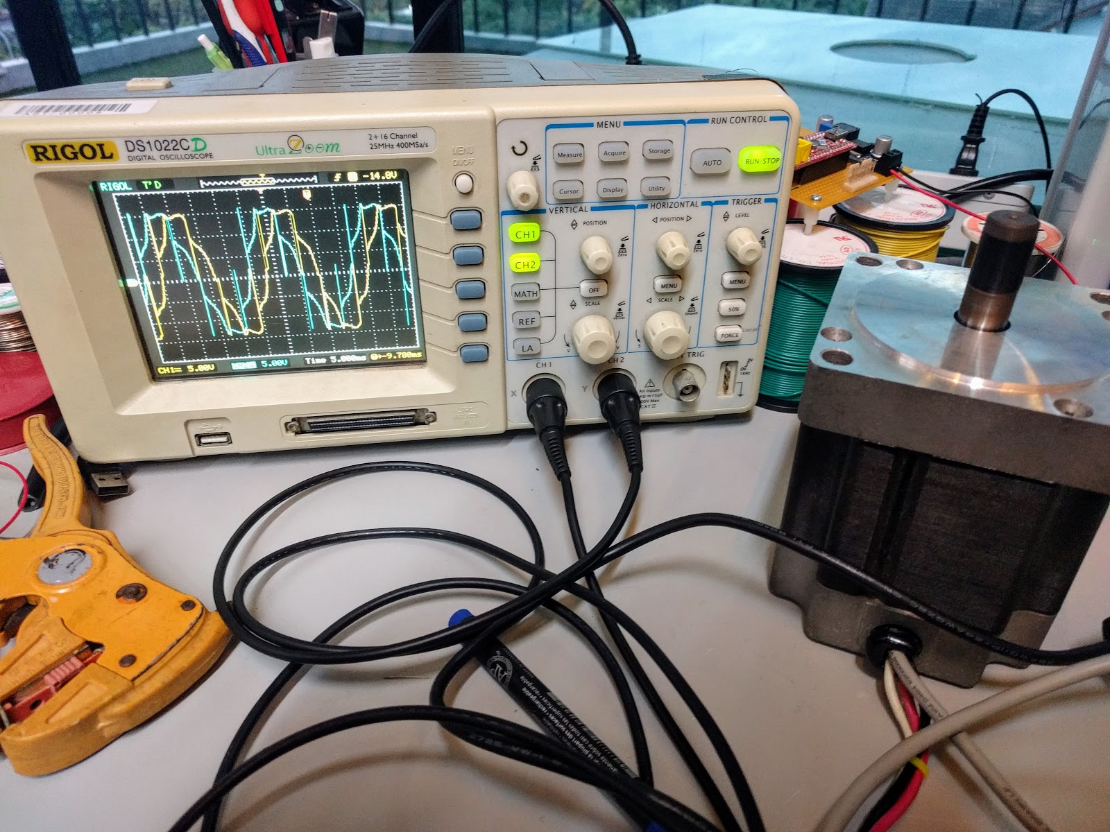
To the left of the microcontroller is the 400W 24V BLDC motor we are testing on, and to the left of that is an oscilloscope that is measuring the voltages on the BLDC motor coils. The motor has 3 inputs (U,V,W), and the scope has 2 channels (A,B), so we are set up something like:

  • A = V-U
  • B = W-U
These are the voltages across 2 out of 3 coils on the motor with the third being V-W. But one can still kind of see this since 
  • A-B = (V-U) – (W-U)
  •         = V – W
So if you can visualize the difference of the yellow and the blue channels on the scope, they you can observe V-W at the same time. Actually the scope might be able to do this, but somehow I remember it only being supported with the logic probes. And since the signals are so symmetrical, it is pretty clear that the difference is going to look the same just phase shifted (as it should be).
Anyway, when we got it hooked up, the motor spun quite smoothly:
Once I realized that we were able to drive the motor without a problem, I experimented with adjusting the voltage on the power supply. Sure enough, it behaved like a DC motor but speeding up at higher voltage and slowing down at lower voltage. As a final experiment today, I reflashed the microcontroller with another version of the firmware that negates the voltage to see if it would spin in the other direction. This was done by simply swapping the control to the lower and upper FETs so that when a drive wire used to be connected to low, it is now connected to high and vice versa. (To be clear, this was done in the microcontroller firmware logic rather than any wiring change.)
And it worked right off the bat also:
Notice how the blue channel leads the yellow channel in the earlier picture, but the yellow channel leads the blue channel in this one. The direction was successfully reversed!
One little thing to point out is the spiky artifacts in the waveform:
Since there are exactly six of these evenly spaced per period (although 1 or 2 of them are less obvious than the others), this is almost certainly occurring at each of the six commutation transitions per cycle. When the Hall effect sensors show a state change, the microcontroller figures out what the new FET gate values should be. But in order to avoid a short circuit by having the top and bottom FETs in a half bridge closed at the same time (think “going from closed to open on top and open to closed on the bottom”, if you close the bottom before opening the top, you will have a short circuit and an exploding FET), a short dead-time is introduced. (In my simple microcontroller test code, this is simply done by pulling low all of the gates that need to be pulled low before pulling high all of the gates that need to be pulled high.) 
As a result, there is a very brief discontinuity in the signal. This is called “dead time”, and can be much shorter than the amount of time shown here, but it doesn’t really hurt anything to make it longer, other than a tiny fractional power loss.
Anyway, now that we have a working test setup to successfully drive a BLDC motor both forwards and backwards, the next things to do are:
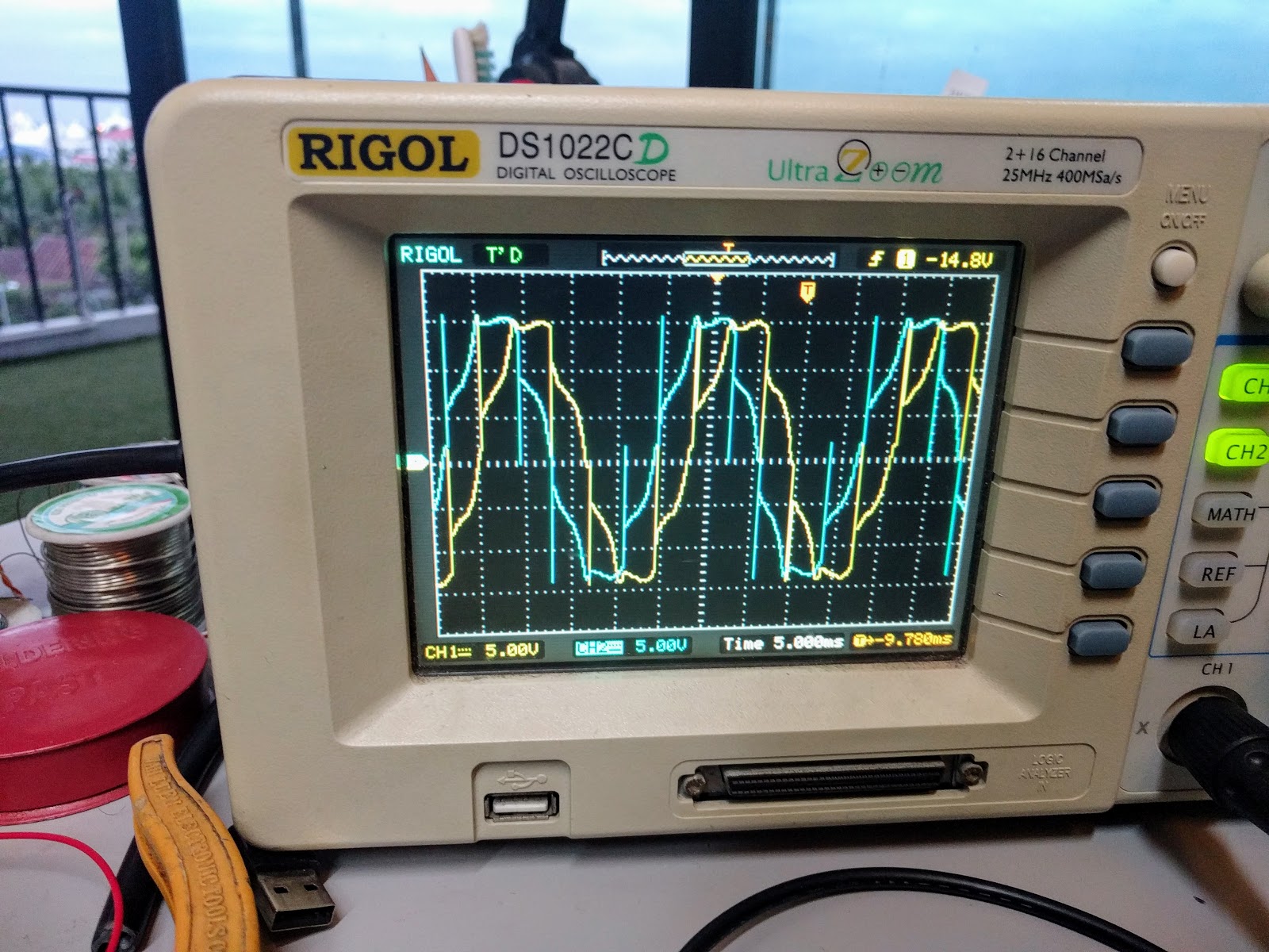
  • Apply PWM control to the gate of whichever lower FET is closed. (There is always exactly one.) If I want to get really fancy, I can try to use the PWM to do velocity control, since the Hall effect sensors already supply the microcontroller with the rotational velocity information. This will be useful for the ferry boat since the large 30cm propeller will need to turn very slowly to provide the required speed, and voltage control at low speeds is very unreliable. (Small changes in resistance in the water can result in large differences in propeller speed.)
  • The test above was done at no-load. Adding a load to the motor will increase the current draw. Larger current draw will mean larger voltage spikes. Once the PWM control is in place, this will mean thousands of spikes per second. The FETs we are using are rated at 200 volts, which leaves a lot of safety margin for spikes compared to the 24V supply voltage. But when we built the DC motor controller for the solar powered pumps, we saw several hundred volt spikes on a 24V supply voltage until we snubbed it. So I may need to add snubbers here, too.