The motors we mounted onto the ferry boat are brushless DC (BLDC) motors. Until now, I haven’t actually successfully built a BLDC motor drive circuit. Mostly it is because we’ve been busy with a hundred other things. But now that the motors are mounted on the ferry boat, and we have to start thinking about the propulsion system for the floating house (BaanLoiNaam is designed to operate disconnected from land), it is time to get the BLDC motors working, or else give up on it and find another route.
I have previously written the simple firmware for the microcontroller to drive the BLDC motors, but we didn’t have the required 3 half-bridges needed to see how it works. Part of this was that we were waiting on some electronic components that were on back-order, but mostly it was that our attention was elsewhere.
Yesterday, I saw that pommm finally found some time to double check that the test boards we had built were wired up as intended:
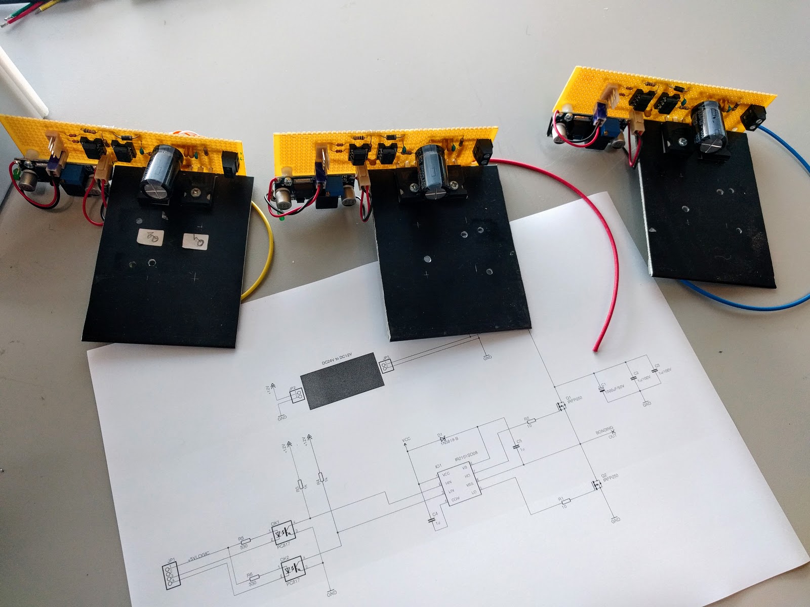
These are three independent half-bridge circuit boards each with a large flat piece of aluminum as a temporary heatsink until we decide on the final form factor. Hopefully I’ll have a chance to test these sometime this week.
As a side note, pommm showed me these BLDC controller circuits he bought off of eBay for a couple bucks to play with:
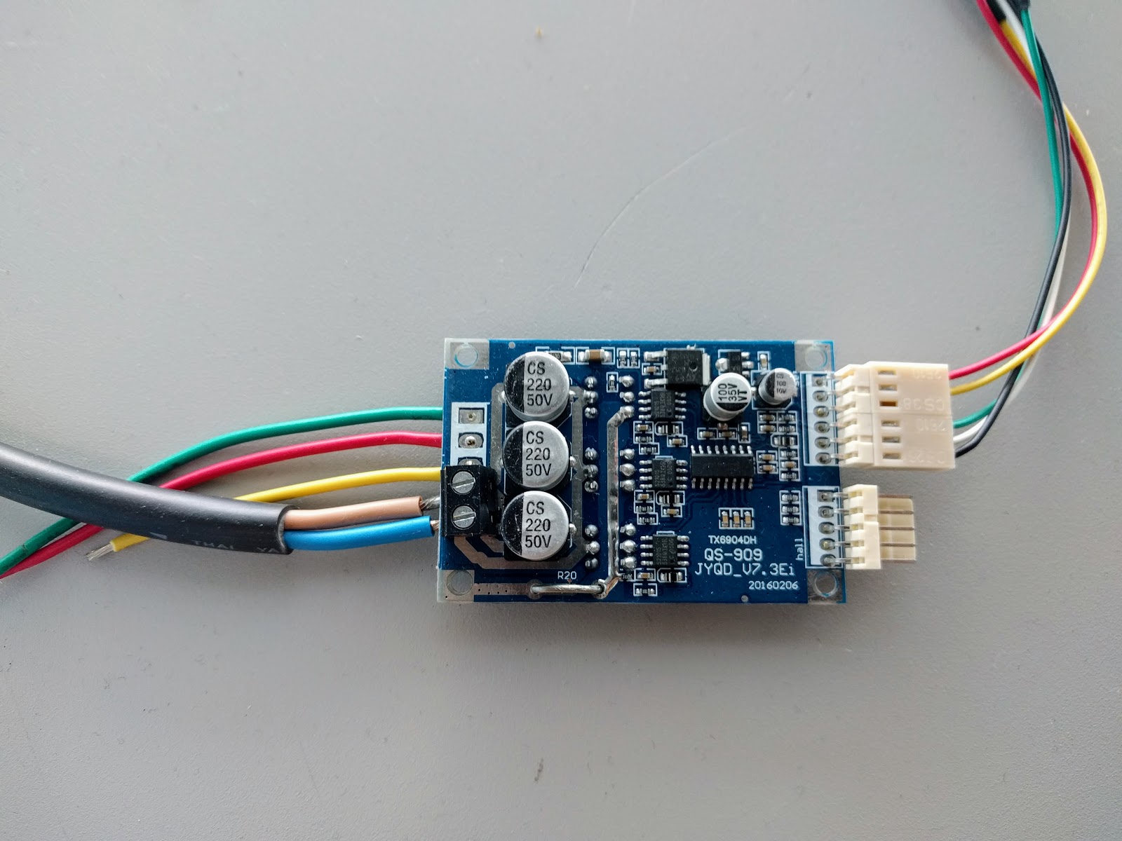
They have a current limit of about 4 amps, which is hopelessly under what we need. (The 800W motors that we have on the ferry boat can sustain something like 20A and probably will peak at 2-3 times that number. And given my druthers, BaanLoiNaam will have motors an order of magnitude higher than this, if we can reliably drive them.) But nonetheless, it is usually good to have a reference case where we can see what the signals look like and how the output waveforms behave on a commercial product for comparison in case we are wondering why our experiments aren’t working.