I’ve been wanting to experiment with brushless DC (BLDC) motors for some time now. Today, I finally got the chance to write the microcontroller firmware to do the logic.
We are still waiting on some electronics to build the 3 half bridges needed to do the power side. But we pretty much finished the control logic. Here is a picture of our setup:
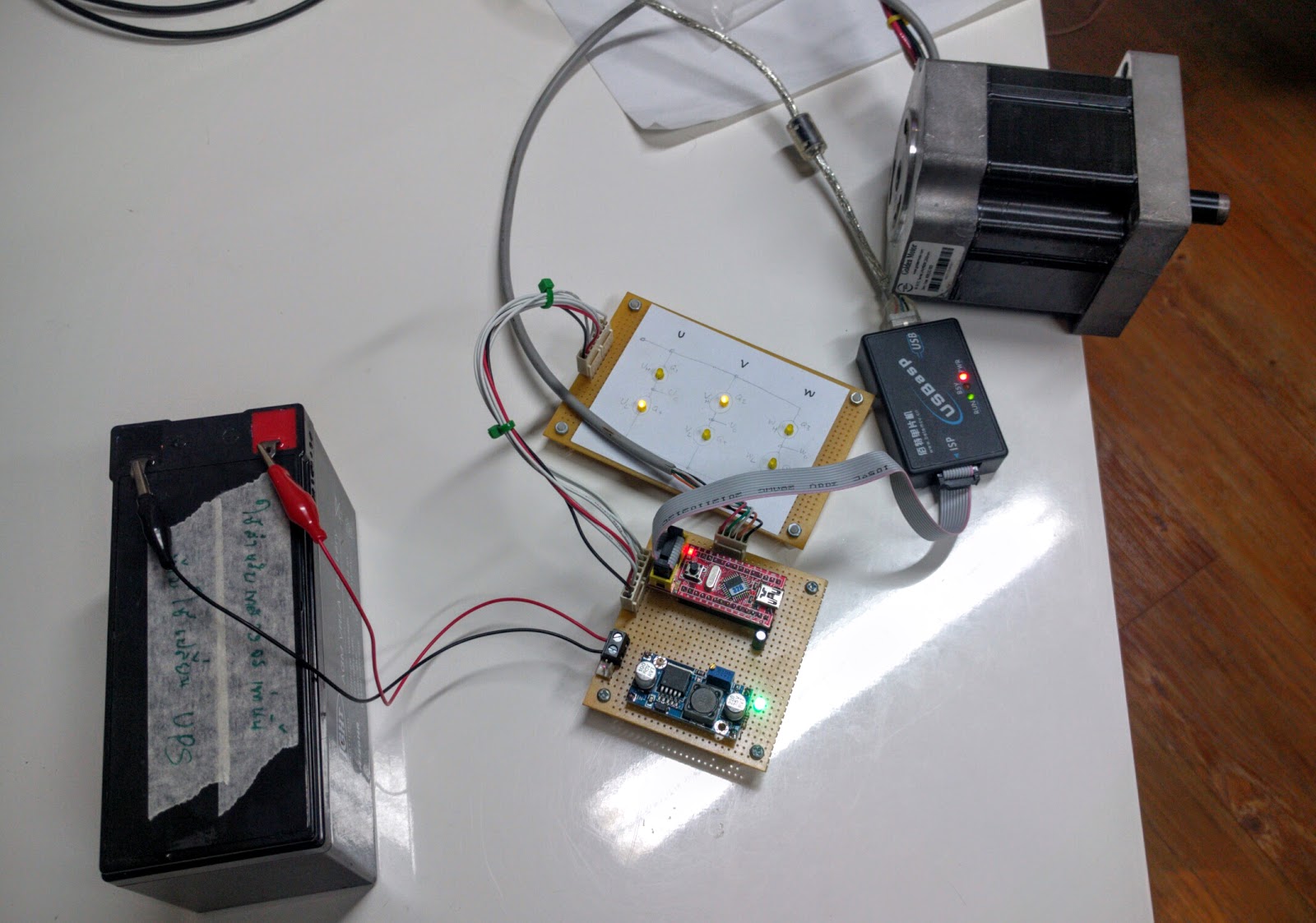
The left is a 12V lead acid battery, the perf board in the middle bottom has an ATmega328 board (red) with a DC-DC stepdown converter (blue) to supply the 5V to the ATmega. The white board above it is simply 6 LED’s that are connected to the pins which will drive the gates on the 6 FET’s we will be connecting up to later. The LED’s allow us to observe the logic as we rotate the motor to make sure we get the sequence and timing (“commutation”) right. To the right of the white board with the LED’s is a black USBASP USB programmer for the ATmega. In the upper right is a Golden Motor BLDC motor (24V 300-400W if I remember correctly).
The only real trick was trying to figure out the correct commutation order. We got the documentation from the motor manufacturer describing the meanings of the hall effect sensor pins coming out of the motor. This allows us to know the current rotation state of the motor. But the goal is to use this information to apply voltage to the three power wires on the motor such that the torque being applied on the motor is always in the right direction.
A brushed DC motor which uses the brushes to reverse the magnetic field on the commutator at the right time in order to keep the torque going in the same direction. The idea is that there are permanent magnets inside the motor and controllable electromagnetic coils on the rotor, and if you don’t change the magnetic fields on the rotor, the motor will spin to a particular position where the magnetic fields on the rotor are aligned with the opposite poles on the permanent magnet. Then it will just stay there. But if you change the magnetic fields at just the right instant, you will continually be applying torque to rotate in the same direction.
In a brushless DC motor, the permanent magnets are spinning on the rotor and the coils are fixed. By using the hall effect sensors to detect the exact angle of the magnets on the rotor, you can control the current flowing through the fixed coils to generate the right magnetic field to keep the rotor spinning.
There are plenty of good YouTube videos to explain this better such as this one
But the problem is that you need to know the relationship between the wiring of the coils and the positions of the hall effect sensors.
pommm and I spent a bit of time trying to figure this out before we stumbled across this link. The basic idea is to connect one of the three wires to Vcc and the remaining two to GND. This applies an attractive force on one coil and a repulsive force on the other two. This spins the motor to a specific angle. Then we read the hall effect sensor in this configuration. Repeat with the other two wires. Now you know the relationship between the coils and the hall effect sensors. 🙂
We used a simple adjustable bench power supply:
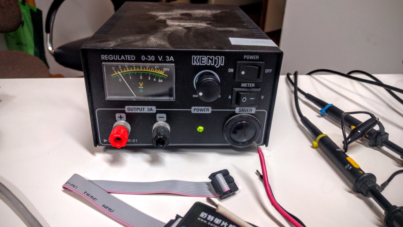
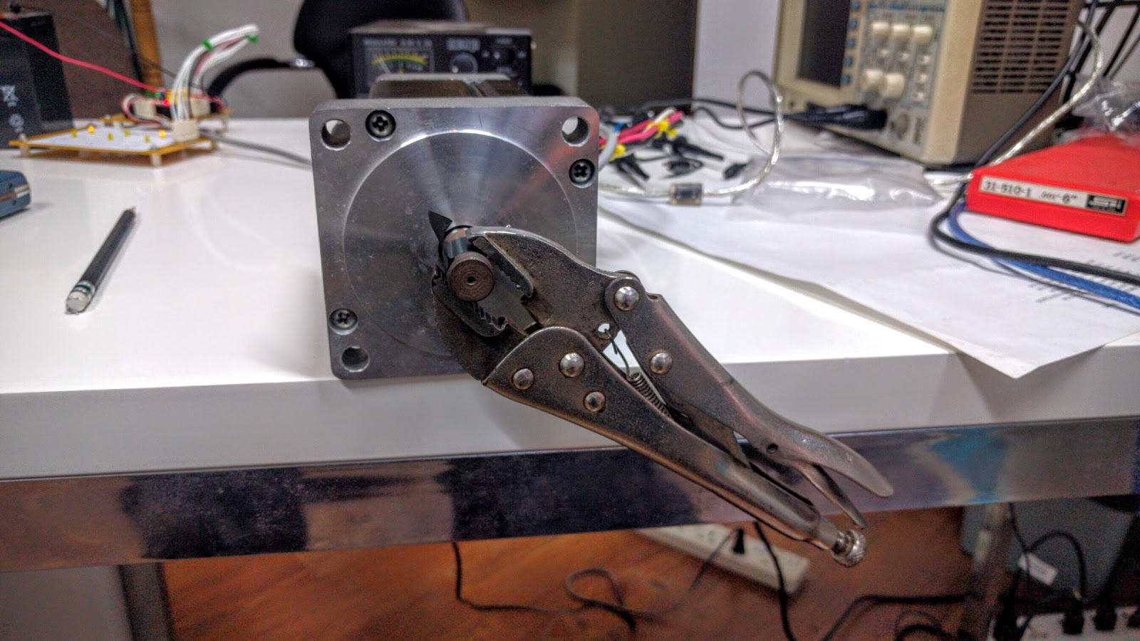
We limited the current to just 2.5A in order to apply an observable but not dangerous amount of torque. Here we affixed a vice grip to the motor so you can see the angle:
To make it easier to read the hall effect sensors, I just had the microcontroller light up the lower 3 LEDs on the white LED board to show the hall effect sensor output voltages:
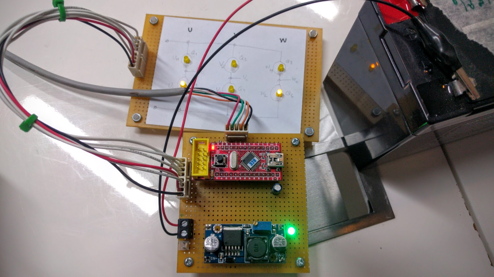
So in this case, we can see that connecting Vcc to this one wire resulted in a hall effect sensor reading of “high,low,high”. The other two wires resulted in “low,high,high” and “high,high,low”. So now we know the relationship between the hall effect sensors and the wires.
The next step will be to wait for the circuitry we need to finish the 3 half bridge drivers and see if we can actually spin the motor.