With all the other things going on, we’d been too distracted to finish the DC solar powered lighting in BaanMae. So while staying there, we had be reliant on plug-in AC lamps. Except in the main room and bathroom where we had been working on prototypes. 
Once we were happy with the prototypes, we sent the PCB’s out for fabrication. They came back about a month ago, but it just went in the queue of the many things we had to get to. So finally, in the past week or two, it rose to the top of the queue, and the lighting is now finished.
Here is a view inside the light controller box:
Each of these boxes contains at 24V->5V switching power supply (mounted on the left side of the box) and a custom PCB for controlling the lights (back face of the box). The PCB holds an Atmel ATmega168 microcontroller programmed to listen to the light switch and dimmer, and control the LED lights. In addition it controls two LED light channels using a power transistor whose base resistor is chosen based on the number of LED’s on that circuit to correctly limit current for that number of lights. These boards also sit on an RS485 bus, so that the lights in the house could be turned on and off remotely should we so decide.
In order to save engineering time, these boards are shared with the smart walkway lights outside. They even run on the same firmware, differing only in the EEPROM configuration. (The walkway lights don’t have directly attached light switches plugged in, but may have motion sensors once we get around to this. Although I’ve been considering using the same motion sensor functionality indoors for the bathroom and outdoor balcony lights.)
We also built our own wall mounted light holders:

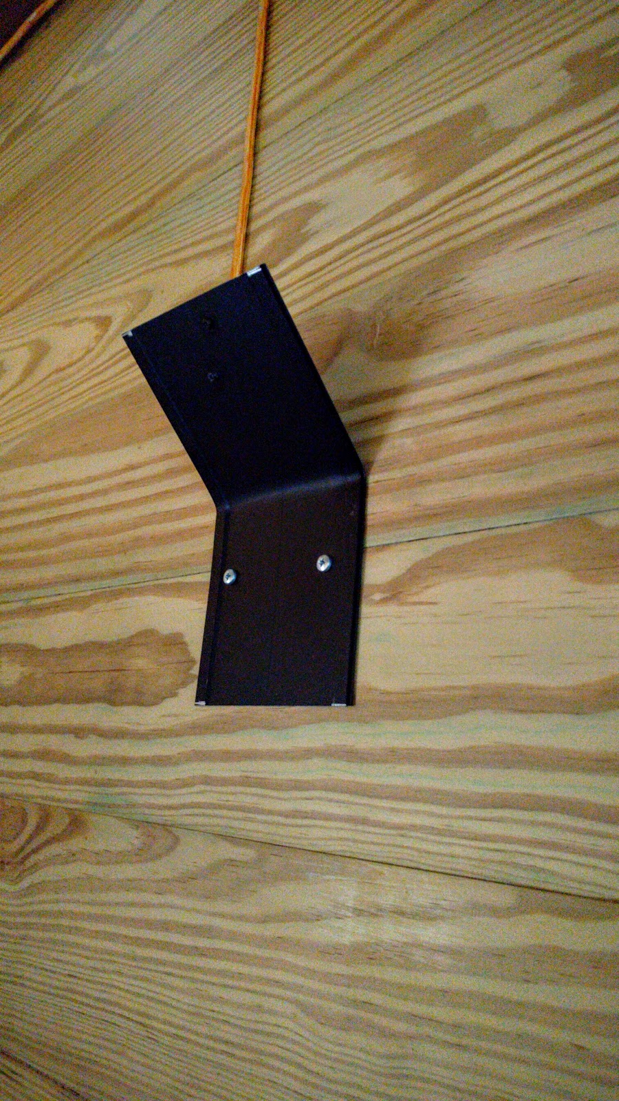
These are made from the same type of aluminum piece that aluminum doors and windows are made from, but bent in the middle. The aluminum both mounts the LED and acts as a heat sink.

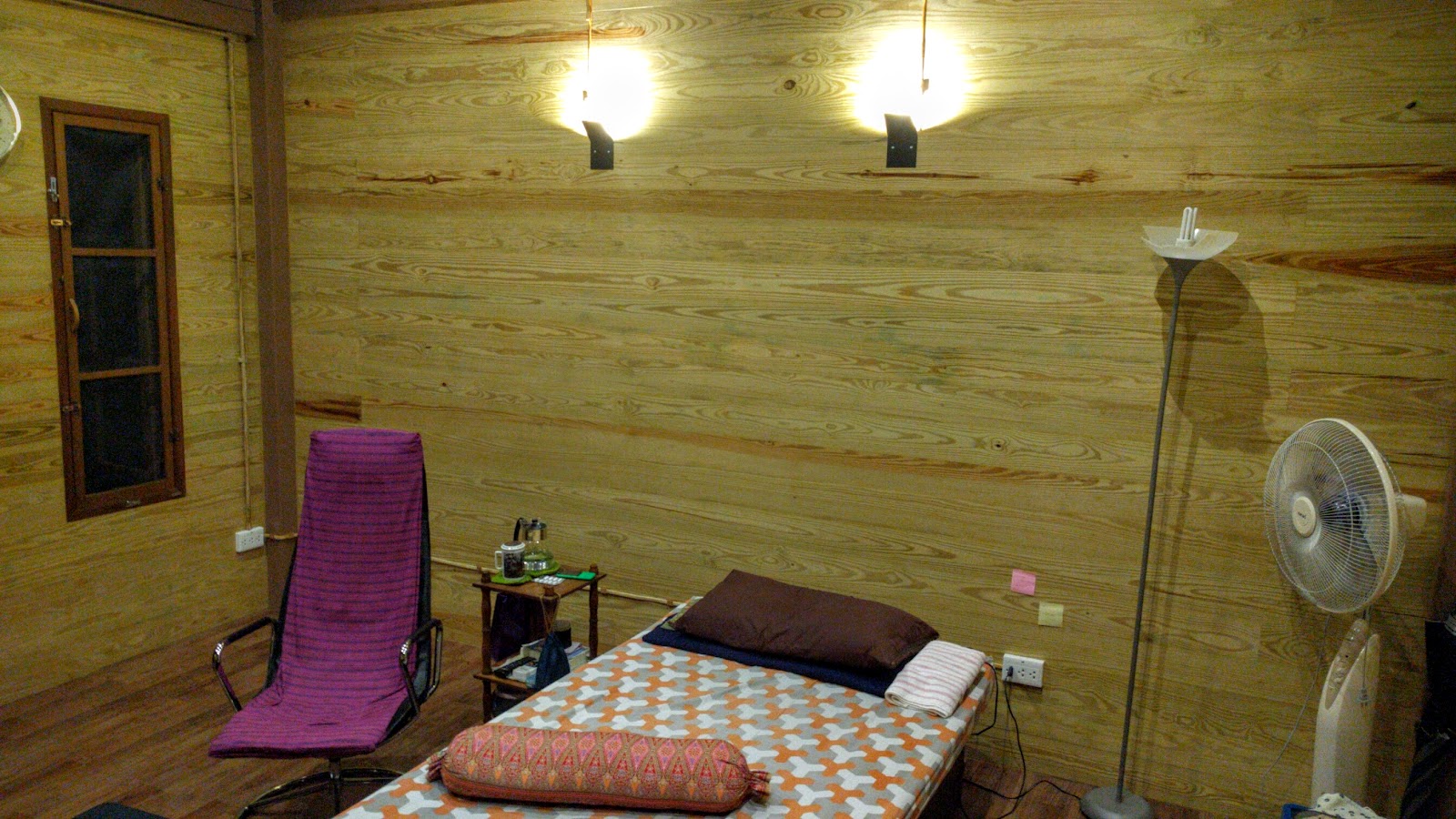
These guys bounce the light off of the wall at about 45 degrees making a nice soft light in the room:

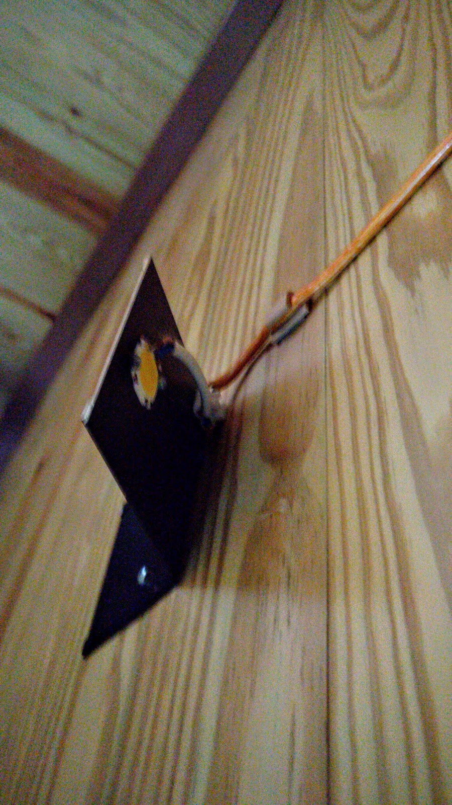
The ceiling lights have gone through a few iterations. The key is that need for a heatsink. We settled on a PCB design that makes mounting the LED easy (solder it on), but also makes wiring easy. The LED is wired to a +24V and GND trace and then wiring connectors are added depending on the configuration around the particular light. Connectors can be added in each of the 4 sides to make end lights (1 connector), straight throughs (2 connectors opposite each other), 90 degree turns (2 connectors 90 degrees from each other), Y splits (3 connectors), or even 4 way junctions. Here is one with the plastic cover removed:

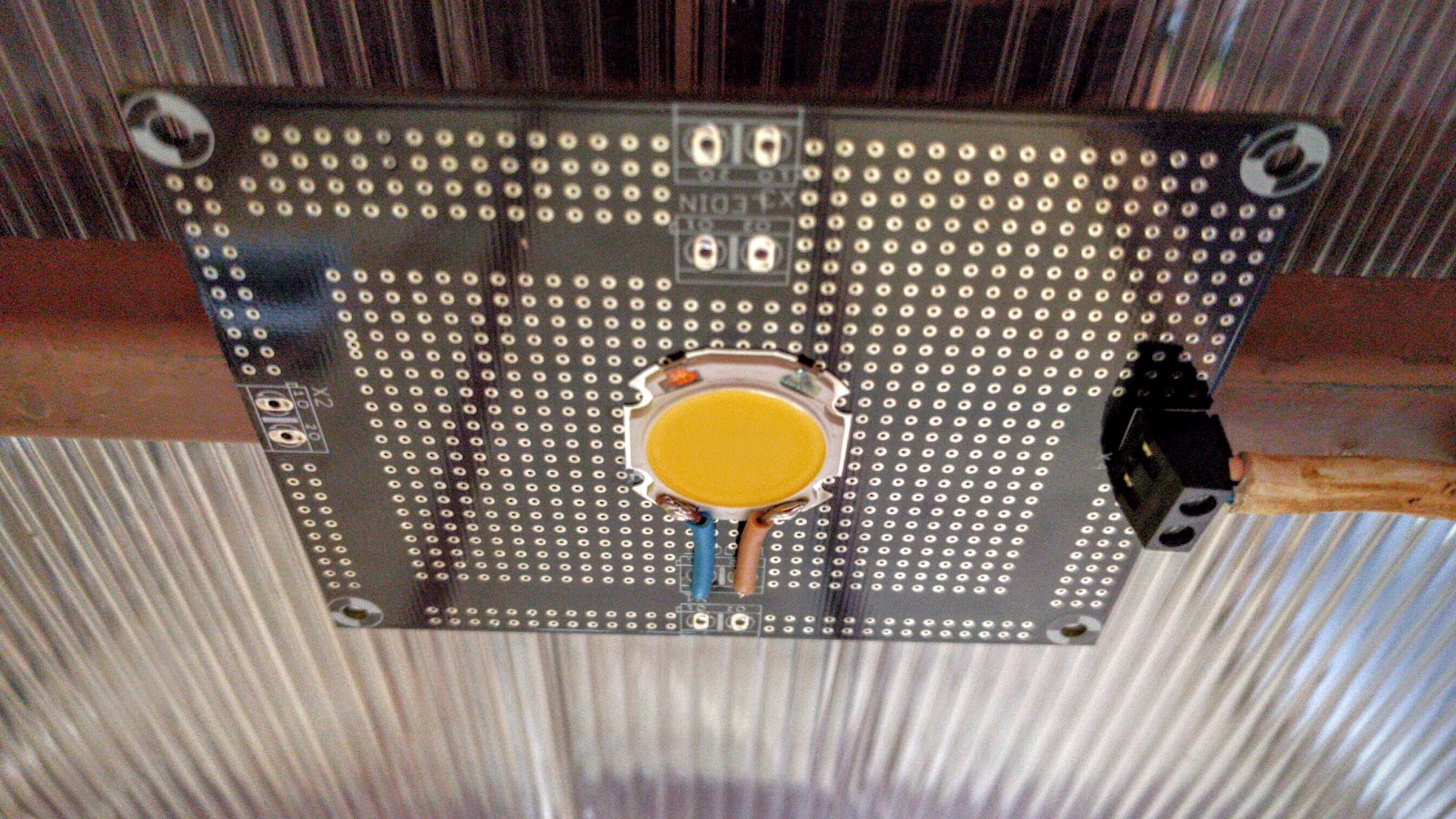
The many through holes in the PCB help radiate the heat from the board. This one is an end light, so it only has one connector.

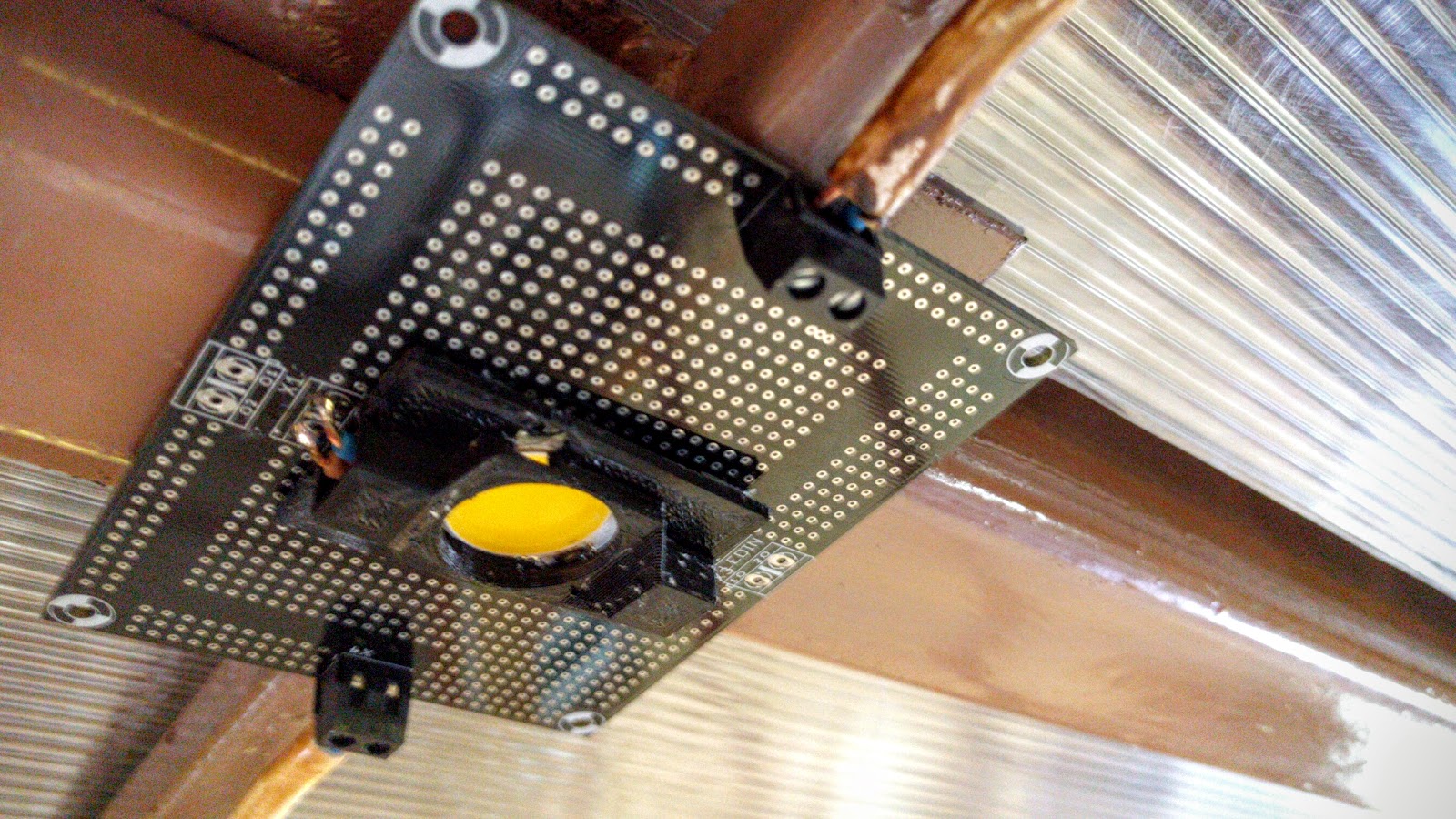
Here is a straight through with two connectors and the 3D printed plastic cover for the LED:

We are now experimenting with an improved design that has a little bit of a cylindrical piece coming down to reduce the glare from the light on the ceiling from across the room.

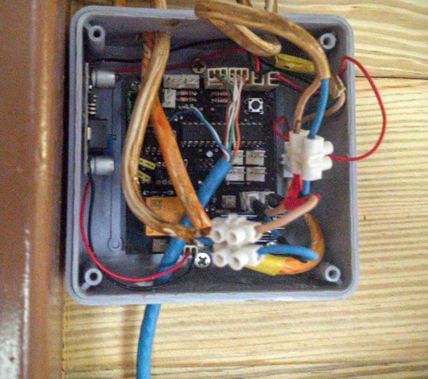
But having light in each room at the flick of a switch is quite nice. And every light in the house is dimmable and powered off of the solar powerd (battery storage) DC circuit, so the lights don’t go off during a mains power out.