I’ve been going around and putting finishing touches on the many projects that I’ve written about previously. I wrote previously about the custom solar powered LED light system that we built, but we hadn’t come up with a nice aesthetically pleasing design for a light switch and dimmer knob to control it.
So we hacked a Haco brand light switch box to do what we need it to do…

The dimmer knob is just a cheap encoder we bought off of eBay mounted on a “spacer” designed to separate the two switches. The switches are normal 220V AC light switches. The two switches and the encoder feed into the digital input pins of a microcontroller via a CAT5 cable coming out the top.
Here is a wider view of the bathroom at night with the lights turned on. The prototype light switch is on the left side:
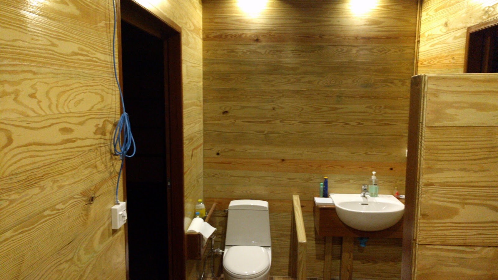
The light switch is mounted slightly low so that my mother-in-law can easily reach it from a wheelchair, but it isn’t permanently screwed in yet. We want her to try it for a few days before finalizing this height. The blue CAT5 cable is just for testing the light switch. Once we finalize the height, we will cut a what CAT5 cable to the exact size and mount it to the wall. Also, we will try to source a nice plastic knob for the encoder that looks right. If not, we can always just 3D print something.
For the bathroom, the control interface is as follows (as determined by the programmed microcontroller firmware):
- The right switch turns the lights on and off via the dimming algorithm described in a previous post
- The middle knob adjusts the maximum “on brightness” of the lights if the lights are on
- The left switch opens or closes a relay that drives the 220V AC bathroom exhaust fan
- The left and right switches each turn on/off different sets of 4 LED lights using the same dimming algorithm (such as wall lights and ceiling lights)
- The dimmer knob adjusts target “on brightness” of whichever lights are on, but does not affect the current saved “on brightness” level of left/right lights if the switch is off (which allows for a simple way to independently control two sets of lights with a single dimmer)