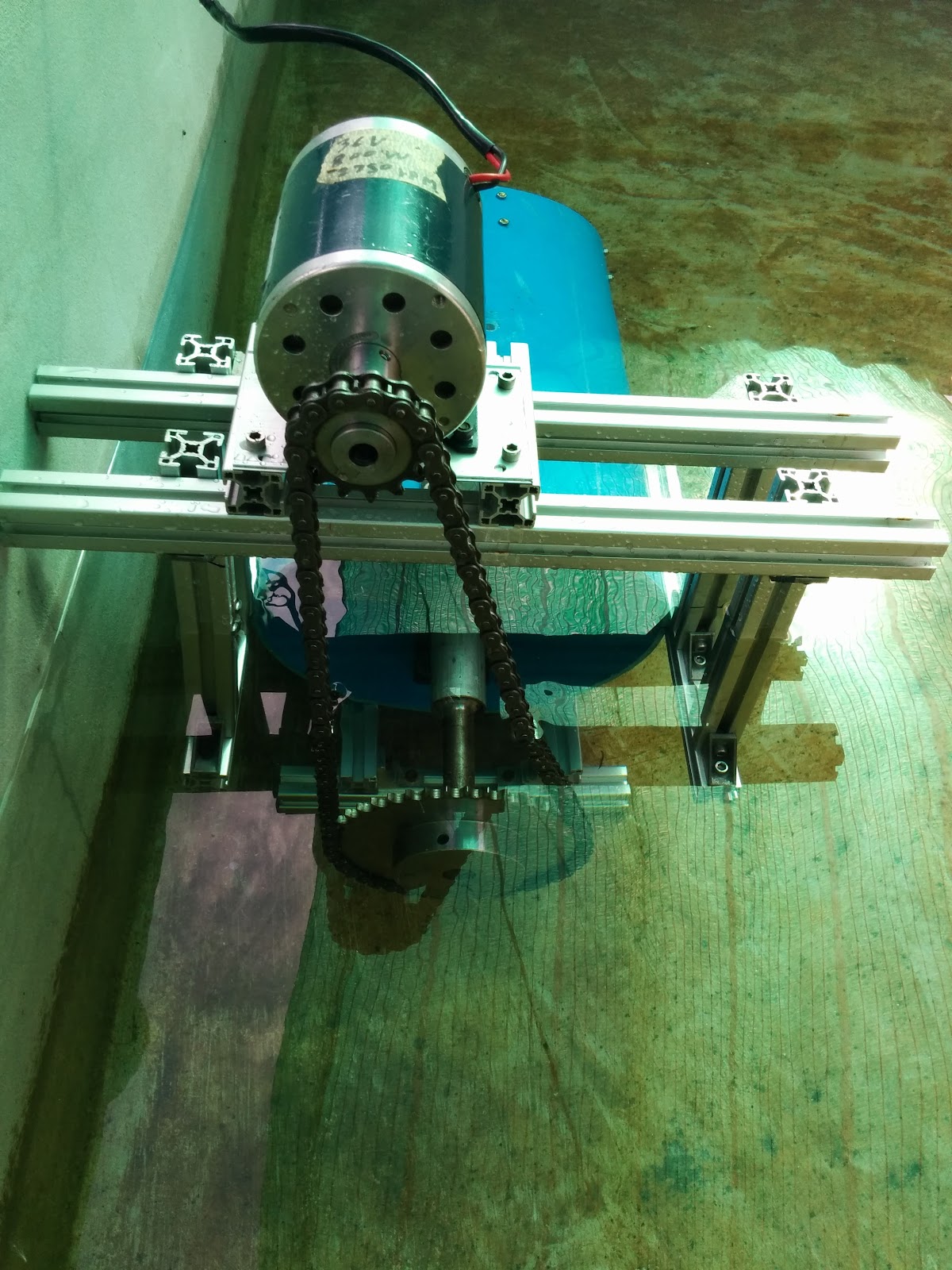
I’ve previously blogged about this simple experimental circulation pump I designed out of a 12″ PVC pipe and a long-tail boat propeller. Well, it took a bit of time to get the motor mounted and everything ready for an in-the-water test. The two slowest parts were machining the coupling between the sprocket and the motor and building a water flow sensor to test it. Here are some pictures of the circulation pump before the test:
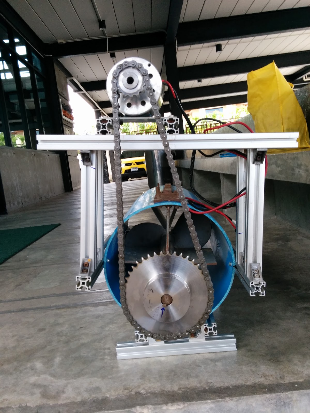
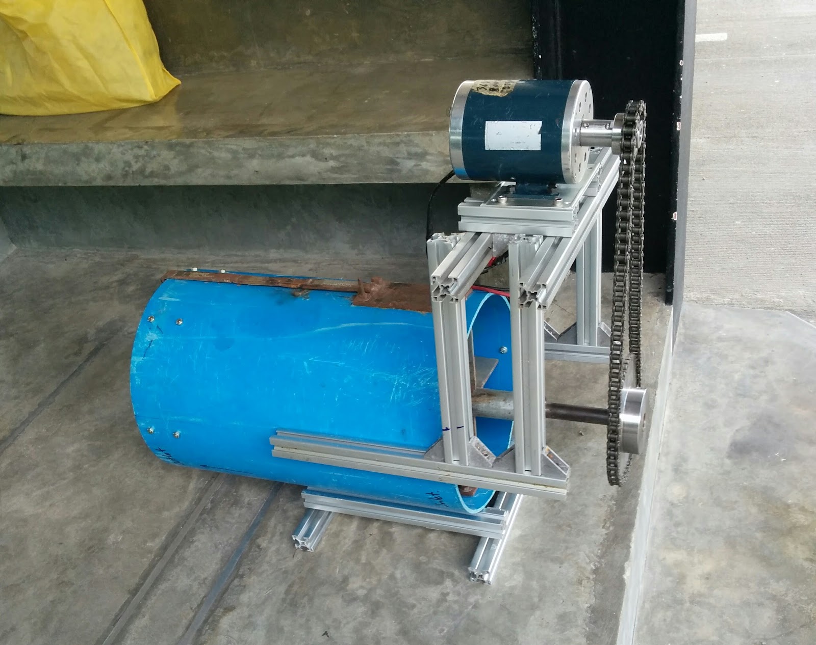
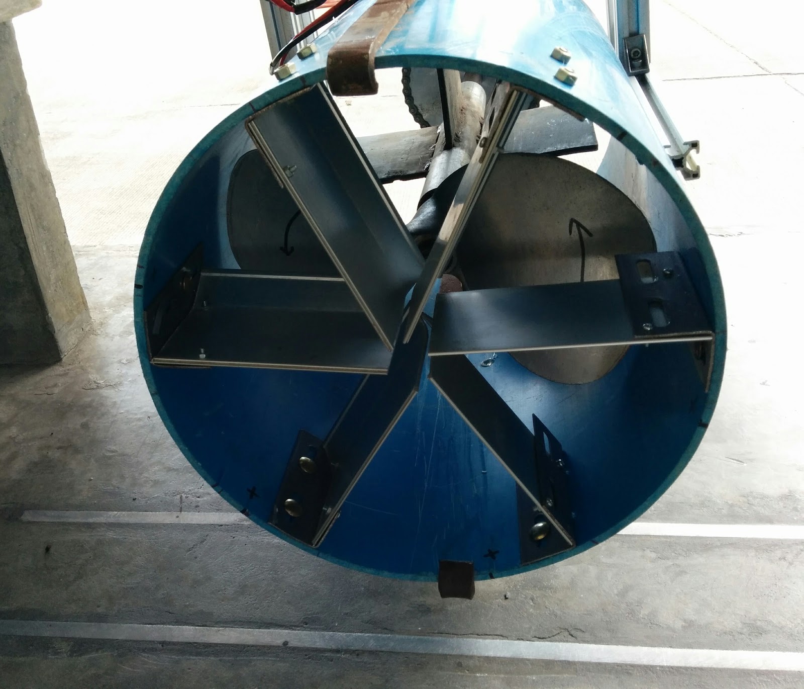
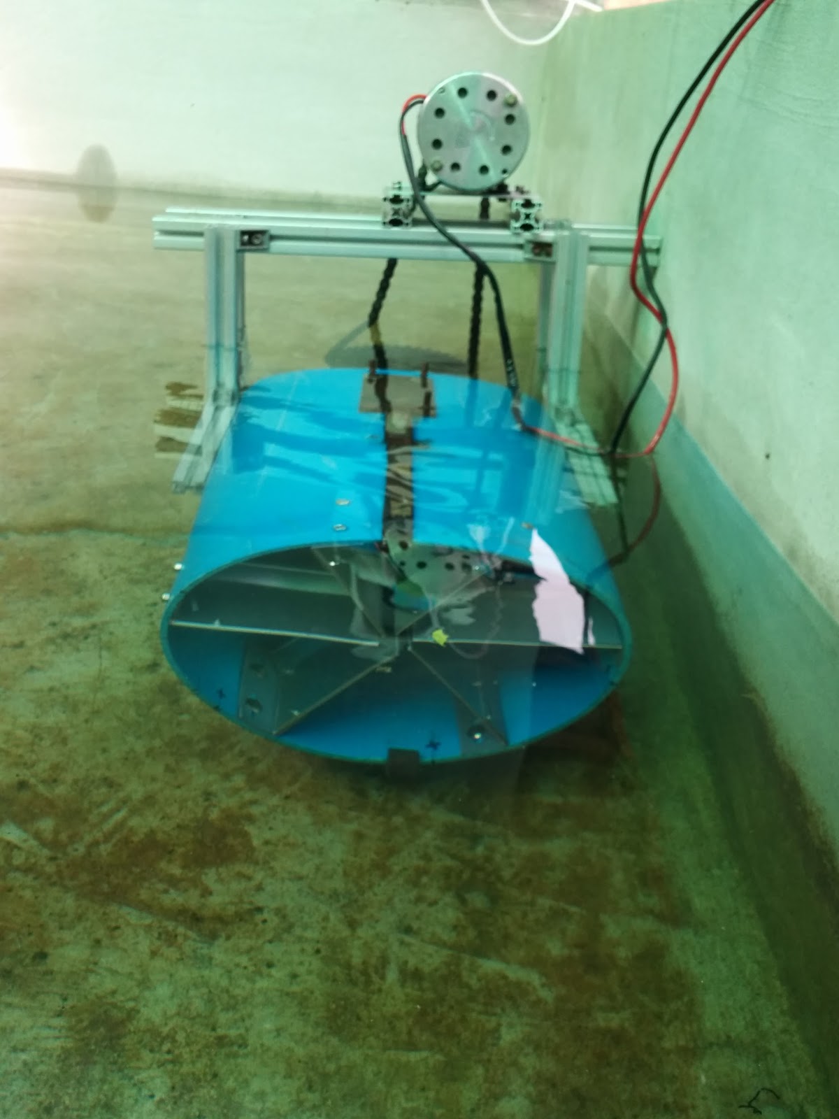
We’ve mounted a 36V 800W DC motor from an old experiment to a quick rough frame made from left-over aluminium profile. In the last image, you can see that we mounted 6 aluminium vanes to the exit side of the PVC pipe with a little bit of curvature to try to straighten out the curved flow of the water coming off the impeller. The chain and sprocket set-up will probably be switched over to a vee-belt configuration for the final assembly so that the vee-belt would electrically isolate the in-water parts from the motor.
Currently, the gear ratio is 3:1, meaning that the 2570 RPM motor is way too fast. So for this test, we are only using a 6-volt battery (vs. the rated 36V of the motor) in order to slow it down. I’m actually targeting about 20-30L/sec of flow for each of the 3 main water pumps in order to get about a 6 hour turnover rate of the pond. Based on my estimate of propeller pitch, in order to get this flow rate I calculated we would only need the speed achieved with about 3V on this motor, but I don’t have access to a high current 3V battery for this test. So for now I am just running it with a small/cheap 6V sealed lead-acid UPS battery we picked up.
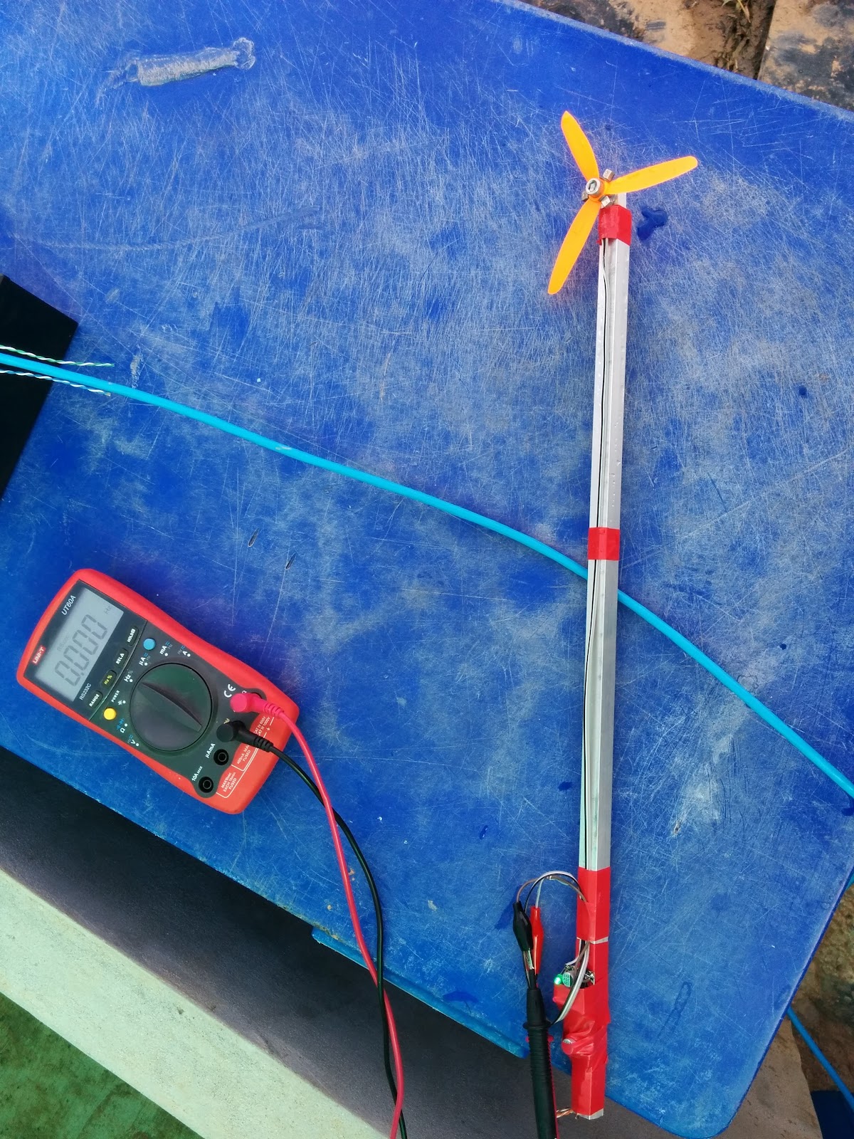
This is a picture of the flow rate meter hooked up and ready to measure:
And here are pictures of the pump in the water before applying power:
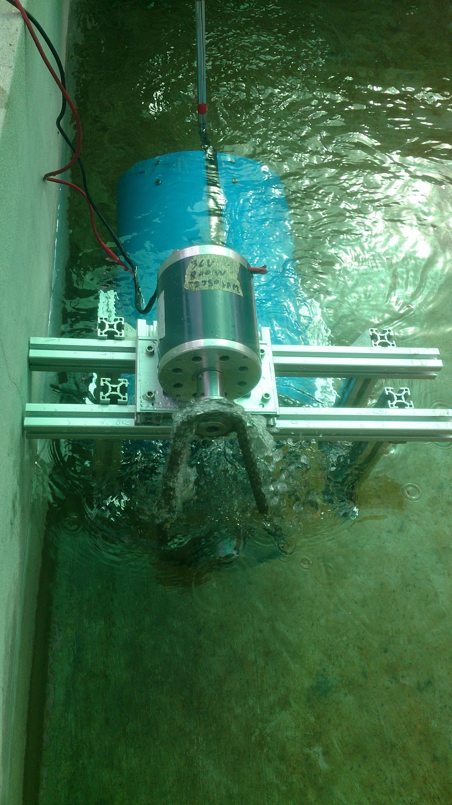
And during the test:
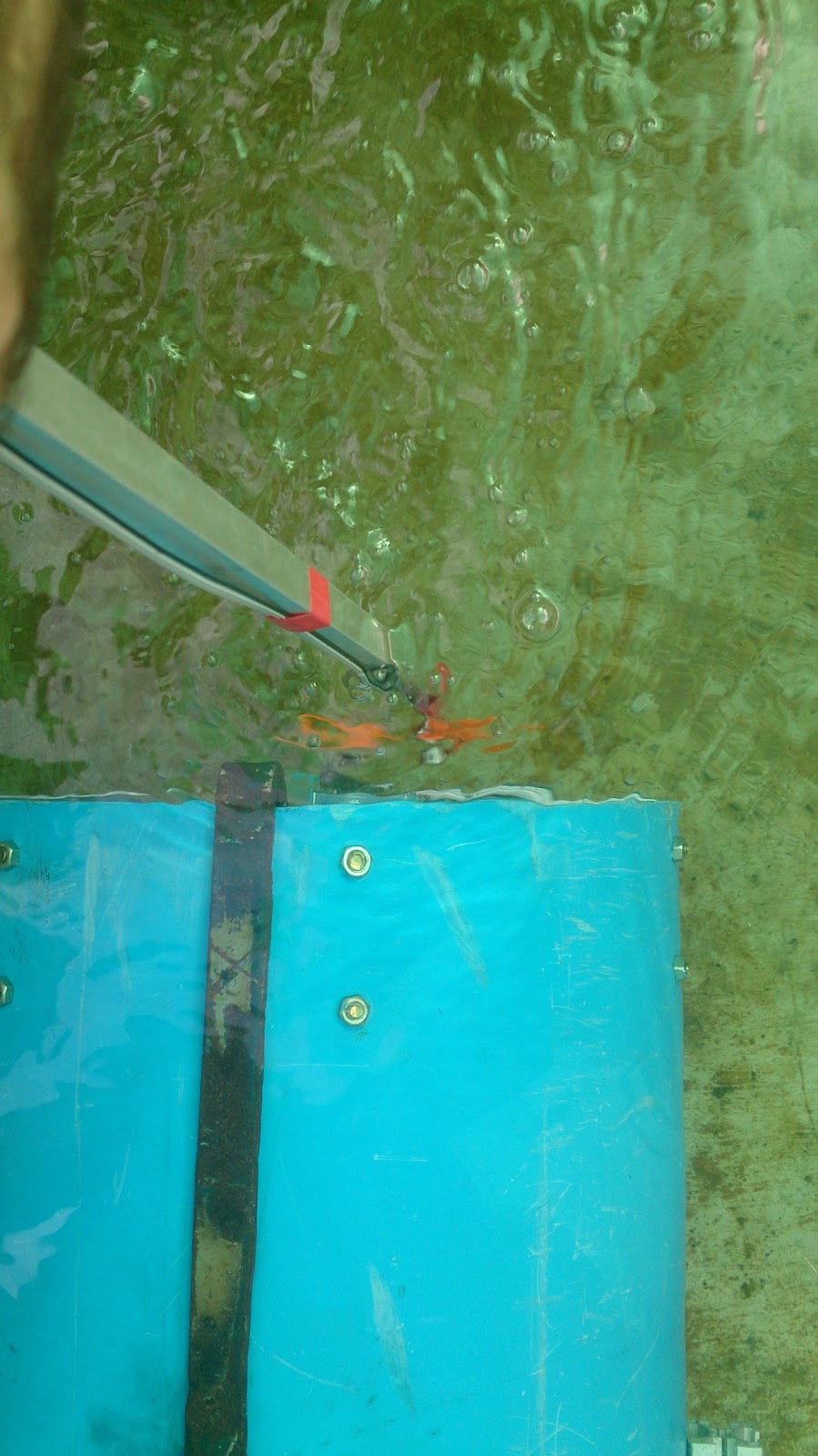
Here is a close-up of the flow rate meter near the outlet of the circulation pump:
And the current measurement during the test:

And here are the measurements (I’m not worried about being too precise since the calibration of the flow rate sensor is probably +/- 10% anyway):
- The motor was drawing about 5.95A (see picture above)
- The battery voltage measured to be 5.92V during operation
- The flow rate sensor varied between 13Hz(center) and 25Hz(edge) as I moved it around the outlet of the pipe, but I’m guessing it was about an 18Hz average based on what I observed overall
- The inner diameter of the PVC pipe was measured to be 31.5cm
- And although it isn’t necessary for the flow rate calculation, I measured the motor to be running at about 7.2Hz with a 3:1 gear ratio to the impeller, so the impeller was running at 2.4Hz (144RPM)
Now that the test is done, we get to do the calculations! Yay!
Power consumption(W) = V*A ~= 6*6 = 36W
Flow rate (cm/sec) = 18Hz * 9.5/3 = 57 cm/sec
Area of the pipe outlet (m^2) = pi/4*0.315^2 = 0.078m^2
So flow rate (L/sec) = 0.57m/sec * 0.078m^2 * 1000L/m^3 = 44.5 L/sec
This is actually much better than I was hoping from this prototype. It appears to be within about 25% of the theoretical amount I calculated from the propeller pitch and motor speed, and I was expecting much larger losses than that.
If you compare these numbers to the numbers I measured on the two commercial pumps I bought a while back, the results are promising. The water flow rate is roughly half of the “pump payanak”, but the power consumption is over 100x less. For reference, (44.5L/sec) / (0.036kW) comes out to about 1200 (L/sec) per kW. This is compared to 22.5 for the “pump payanak” and 10.5 for the large aquarium pump.
Just to remind you, the “pump payanak” was pumping the water up about 1.5m before dropping it back down, so it is quite reasonable that it would consume much more power for the same flow rate. But since I’m only circulating water, not pumping it up, this was almost all wasted work done.
Almost, but not entirely…
Now the main concern I have is that during this test, the water was circulated without any real backward pressure at all. But if we are targeting 20-30L/sec water flow rate from the cistern to the pond, my calculations suggest that the water in the cistern will stabilize at about 10cm lower than the water in the pond as the cistern needs to be fed water from the pipe from the “regeneration zone”. So this will result in a 10 cm water height back pressure. I haven’t taken into account any pressure losses from the sand, either, but I’m hopeful that these slow flow rates (relative to the 1000m^2 of regeneration zone surface area) won’t result in much overall resistance.
10cm head isn’t very much at all, but we weren’t too carefully in making the propeller fit precisely within the PVC pipe, so there are places for the water to slip backwards. And this kind of propeller design really isn’t designed for much back pressure. I guess we’ll see once it is deployed.