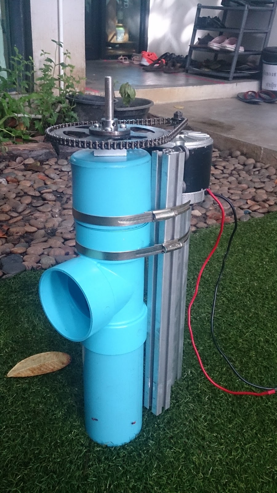
We’ve done our first successful test of the prototype water pump with a 3D printed impeller. Here is a photo of it running:
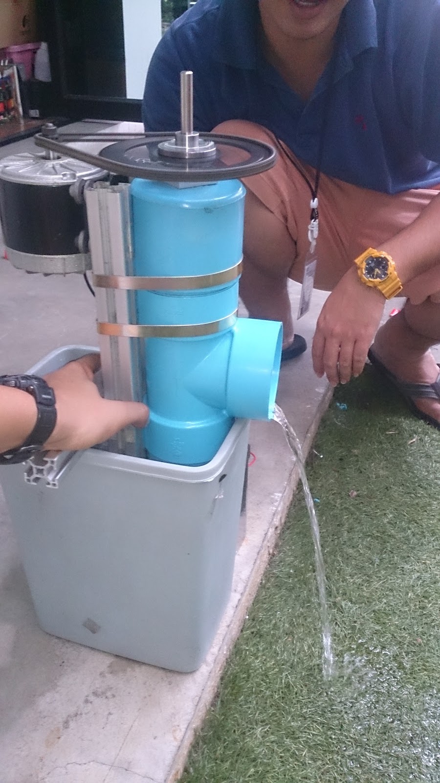
Full disclosure: I’ve been quite busy these last two days, so this successful test was done without me. I’ve just been involved remotely via Google hangouts. 🙂
Kudos to the team!
We haven’t measured the flow rate yet, but I think it looks pretty good for a first test. I’m very pleased with these preliminary results.
We measured the electrical power and found that it is using about 40W in this configuration. A quick internet search shows that a 40W AC aquarium water pump gets somewhere in the 0.5 to 1.0 liter per second max flow rate (at zero head, presumably). I don’t think we are that far off from these numbers at what is currently about 20cm or 30cm head.
For any of you that know me, you might have heard me use the phrase “first light” before in the context of project development. When exploring a new idea, I tend to attempt some kind of quick result (“first light”) so we can then have a more informed discussion of how to proceed in earnest. In short, I like to do the real “project planning” after we are informed by an initial test result.
After reviewing the results of first light, we can begin to ask questions and research the various issues involved in order to understand and plan for a more functional prototype. Looking at actual first light results may precipitate a complete rebuild, or it may just need minor tweaks before full deployment. But in my experience, before first light, it is very difficult to plan a project.
Now that we’ve seen first light, we aren’t anywhere near the potential for this kind of axial flow water pump, but I think it was a very successful start. At these low head levels, an axial flow water pump should get significantly higher flow rates than a centrifugal flow aquarium pump of the same power. On the other hand, we were able to demonstrate that a quick and unscientifically designed 3D printed impeller was successfully able to pump a useful flow of water. Now we need to do some reading up on this more and then experiment with different impeller designs, different spin speeds, and different guides to control the water motion inside the pump.
Here are some pictures up to this point…
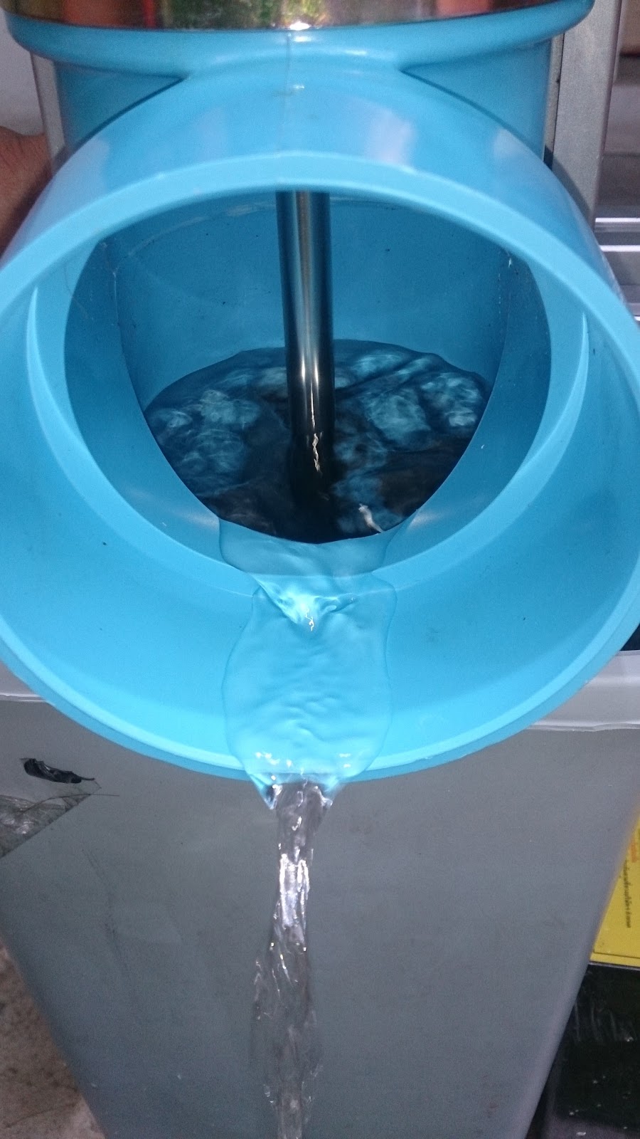
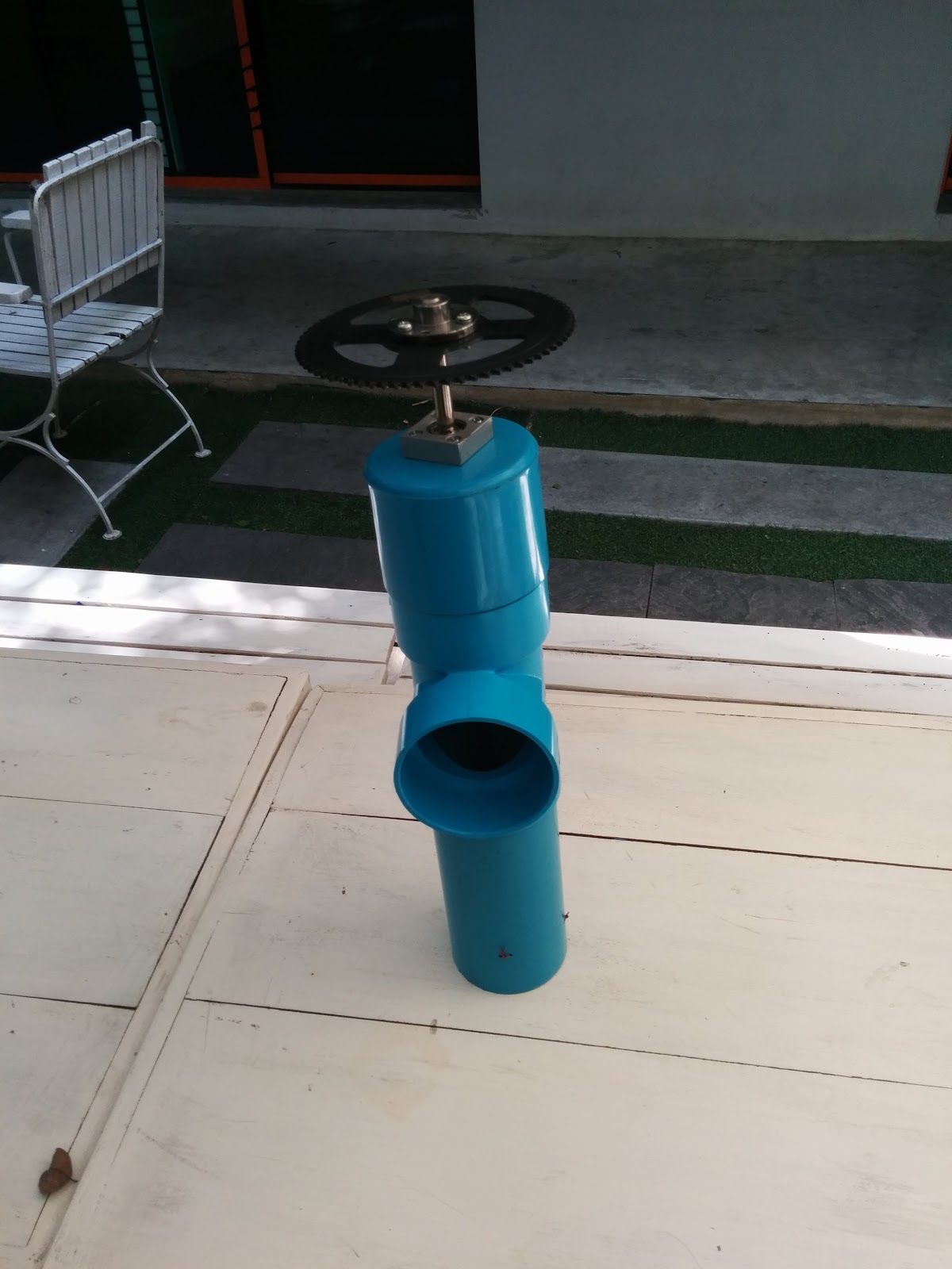
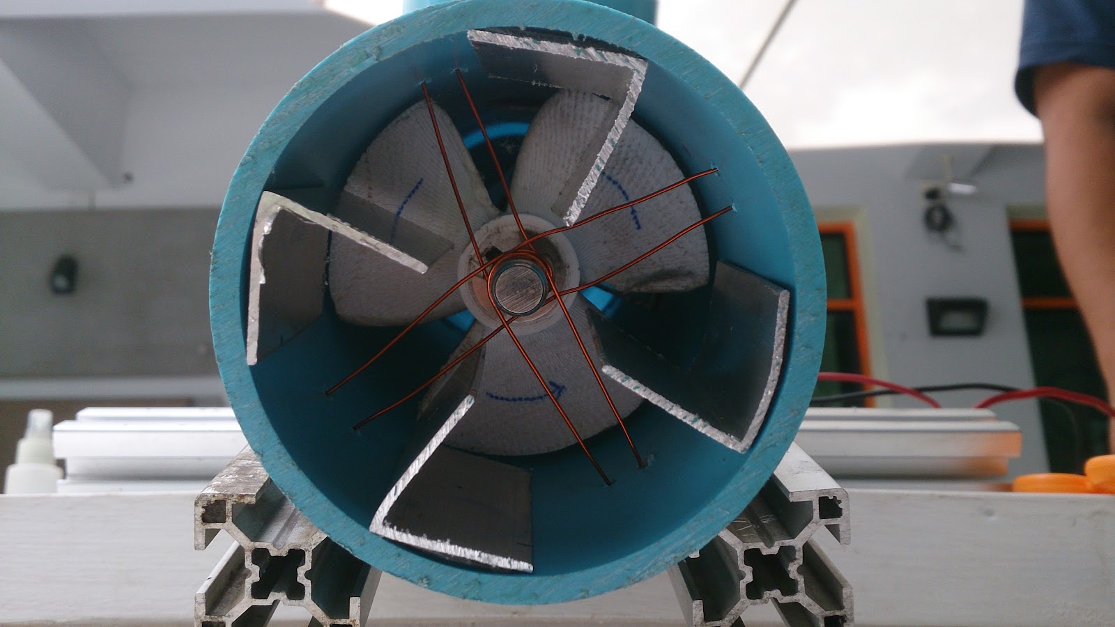
Impeller mounted inside the PVC pipe with sprocket on the top:

Notice the way they mounted the bottom of the impeller shaft with metal wire. I would have never thought of this, but it is easy, and it appears to work quite well. (On top, we are using a bearing from the same project we pulled the motor from.)
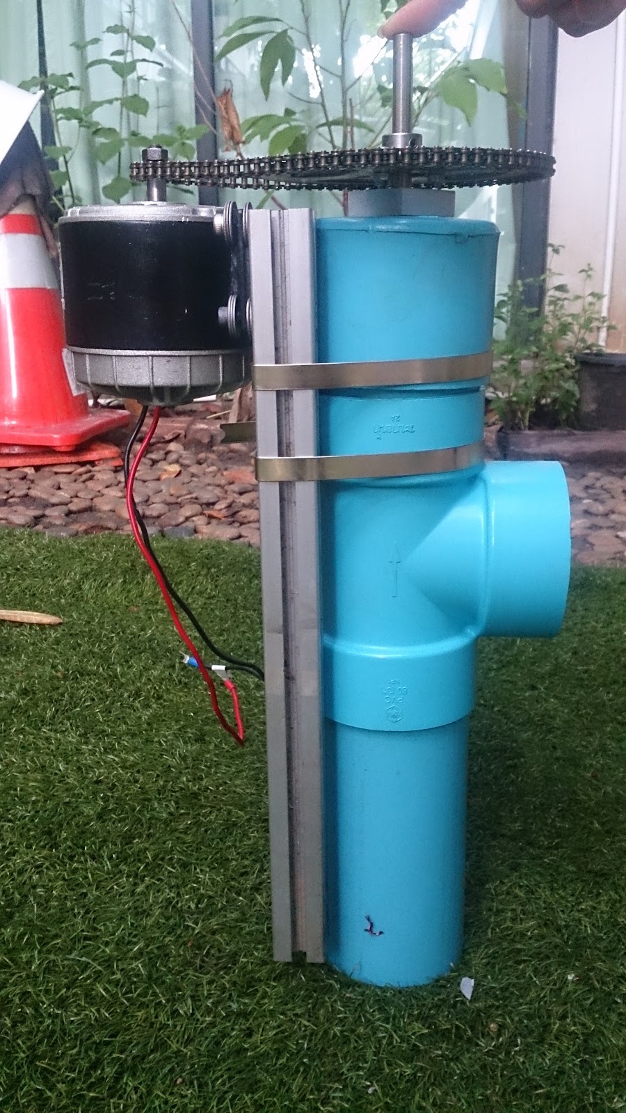
An old 350W DC motor from a previous project mounted with sprocket and chain:
When we tested in this configuration, not much happened. The head level was just a couple of centimeters. This led me to think that the impeller was acting more like a blender just spinning the water around inside the PVC pipe, so we added simple aluminium “blades” to guide the water flow and resist “spinning”.
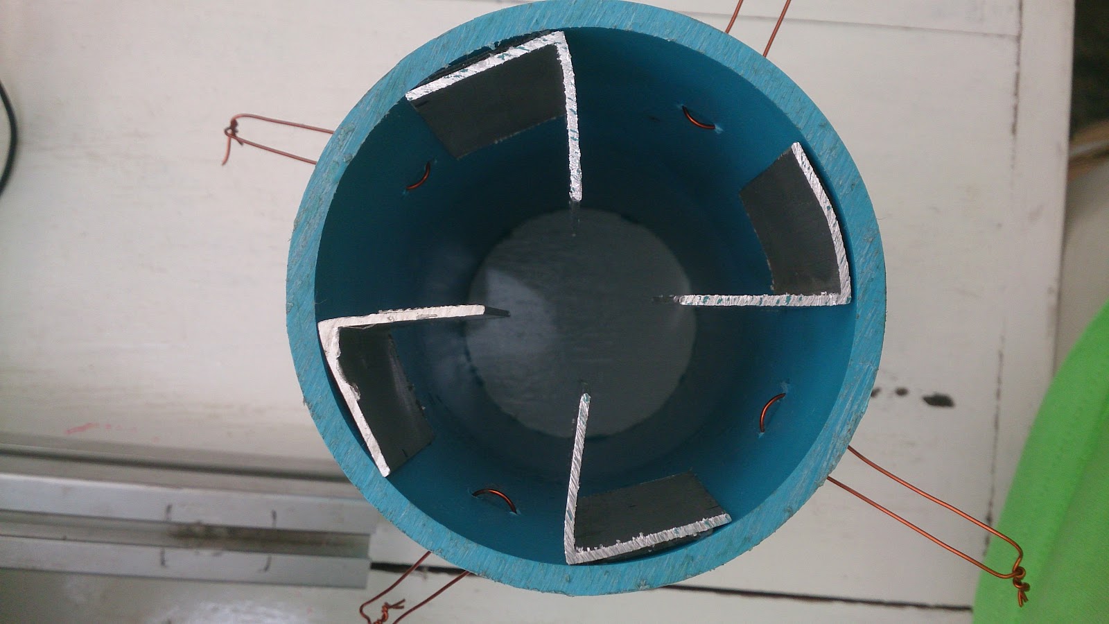
We added these “blades” both above the impeller:
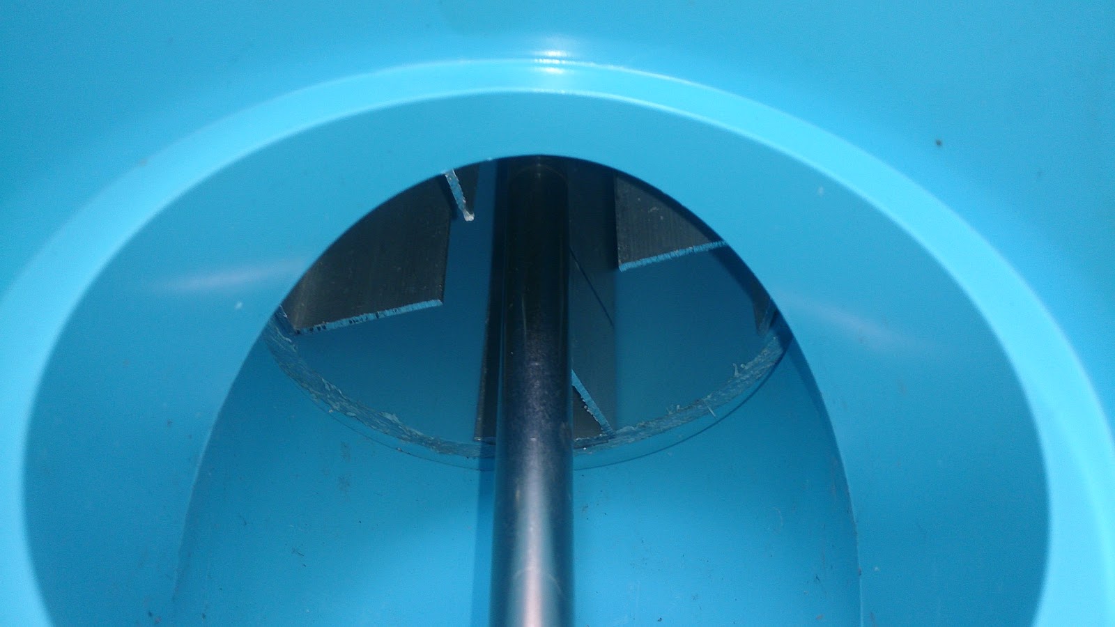
and below the impeller:
and this is the configuration in which we got a successful “first light” test.
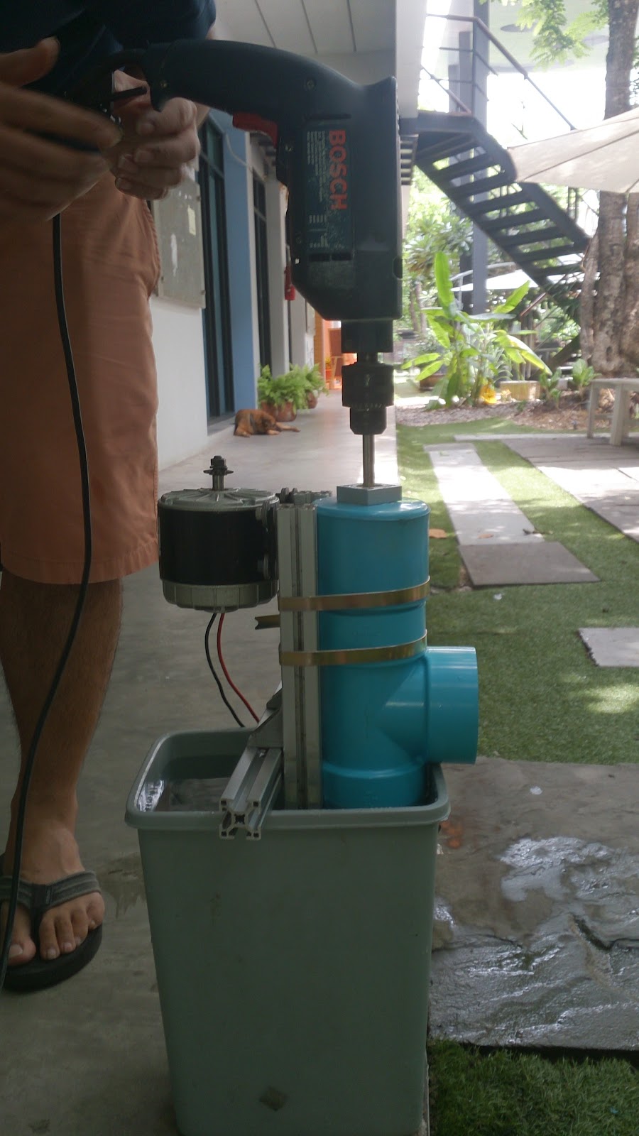
As an experiment, they also tried directly coupling the impeller shaft to a variable speed power drill to explore how flow rate varies with speed. Here is a picture:
Not bad for such a quick project build. Hurray for FreeCAD, 3D printing, PVC pipes, and old parts laying around!